pixalynx/pixal-nfc-card
This code defines React components representing specific electronic hardware components—namely, a 100-ohm SMD resistor, a surface-mount LED, and a chip with labeled pins—each modeled with detailed footprints, 3D CAD models, and manufacturer part information for PCB design.
- Version
- 1.1.0
- License
- unset
- Stars
- 0
docs/MECHANICAL.md
# Revision B mechanical envelope

The PCB has the ID-1 plan outline (85.6 × 54.0 mm, R3.18); this is not a claim of ISO-compliant finished card thickness or flex performance. Board nominal thickness remains 0.6 mm. U1 is the only mounted part; nominal package height 0.55 mm, maximum 0.60 mm. The assembled card is approximately 1.15 mm before solder and protection, locally at U1.

Proposed protected finished envelope, to validate with an enclosure supplier:

| Contribution at U1 | Maximum budget |
|---|---:|
| Finished PCB, including specified tolerance | 0.70 mm |
| U1 package | 0.60 mm |
| Assembled solder stand-off allowance | 0.05 mm |
| Top insulation/protection over package | 0.15 mm |
| Bottom nonmetallic covering | 0.10 mm |
| Total local envelope | 1.60 mm |

The 0.05 mm stand-off and protective layer allocations are design allowances, not guaranteed process values. Measure first articles and revise this budget if the selected construction exceeds it. A standard 0.76 mm total card cannot contain this FR-4/package stack.

Reserve a protected local region x=10.5..16.5 mm, y=-4..+4 mm about U1. A nonconductive local cover or qualified encapsulant must prevent direct pressure/shear at the IC and avoid trapped moisture; its exact material/process is not selected. Keep the entire antenna area and surrounding 1.275 mm-plus margin free of metal foil, metallized ink, magnets, batteries and conductive adhesive on either face. Ordinary wallet proximity to other cards or metal is a test condition, not an assured use case.

Do not describe this thin rigid FR-4 card as flexible. Handle and depanelize with support. Proposed screening: inspect dimensions/thickness and package protection on all 10 prototypes; perform 100 normal wallet insertion/removal cycles and 10 one-metre drops onto wood from varied orientations on at least 3 covered samples, then inspect and repeat RF/phone tests. Zero cracked copper, lifted package, delamination, exposed sharp edge or new required-use read failure is the initial acceptance gate. Do not impose a bend-radius qualification until a required bend load/radius and construction are defined. These screens do not establish lifetime or environmental certification.
Related Packages
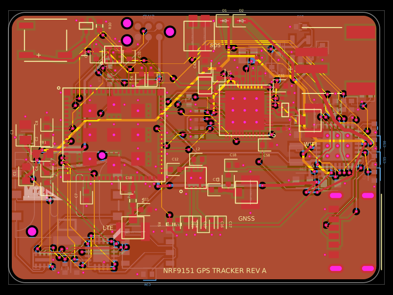 More from this authorpixalynx/nrf9151-gps-trackerA compact 44×32 mm, 4-layer nRF9151 LTE-M/NB-IoT/GNSS tracker PCB with nPM1300 LiPo/USB-C power, nano-SIM/eSIM switching, nRF7002 Wi‑Fi scanning, accelerometer, antennas, buzzer, LEDs, SOS button, and SWD/debug connectors.
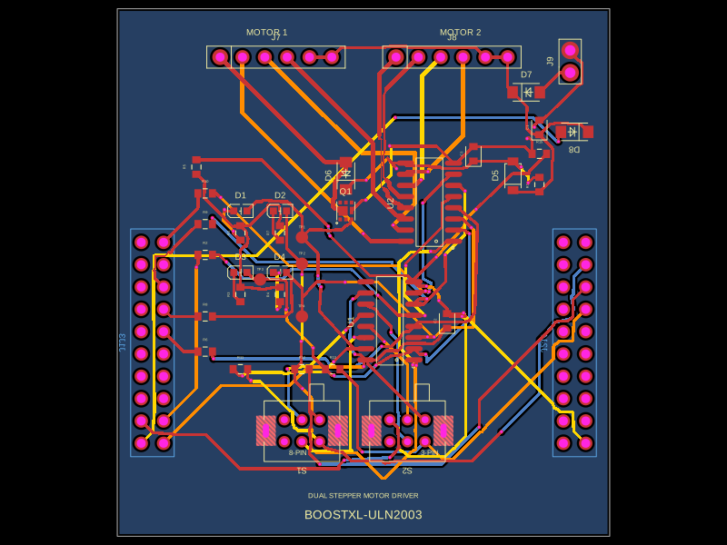 Similar packageabse/boostxl-uln2003This code defines a React component that models a through-hole or surface-mount LED with specified pin labels, footprint, silkscreen, and 3D CAD model for PCB layout.
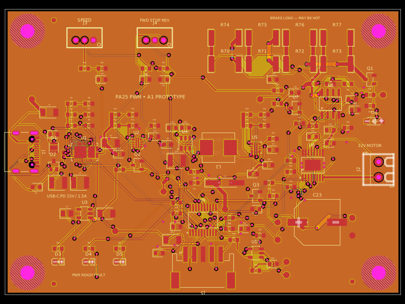 Discover something newAnasSarkiz/usb-c-pwm-pa25A component library defining an AO3400A N-channel MOSFET, 47 µF polarized capacitor, 3-pin through-hole connector, and 9.1 V Zener diode with PCB footprints and 3D CAD models.