pixalynx/pixal-gps
These files define two separate printed circuit boards: a small, two-layer battery cartridge with protection circuitry and contact pads for a pouch cell, and a larger, two-layer wireless charging dock featuring USB-C input, a resonant coil, and wireless power transmission components.
- Version
- 0.1.2
- License
- unset
- Stars
- 0
research/nrf9151.md
# nRF9151 SiP — hardware research report for a fabrication-ready PCB

Compiled 2026-09-14 from official Nordic Semiconductor sources only (docs.nordicsemi.com,
nordicsemi.com, devzone.nordicsemi.com staff answers, Nordic's own hardware-file downloads)
plus LCSC/JLCPCB/jlcsearch for availability. Every number carries the URL it came from.
Anything not found in an official source is marked **UNVERIFIED**.

Source-document shorthand used below:

| Tag | Document | Root URL |
|---|---|---|
| PS | nRF9151 Product Specification (HTML) | https://docs.nordicsemi.com/r/bundle/ps_nrf9151/ |
| HDG | nRF9151 Hardware Design Guidelines (bundle nwp_056; rev history: first release Dec 2024, updated Jul 2025, Oct 2025, May 2026) | https://docs.nordicsemi.com/r/bundle/nwp_056/page/wp/nwp_054/intro.html (rev. history: https://docs.nordicsemi.com/r/bundle/nwp_056/page/wp/nwp_056/revision_history.html) |
| ARF | nRF91 Series Antenna and RF Interface Guidelines (bundle nwp_033; June 2024 update covers the nRF91 Series, examples use nRF9160) | https://docs.nordicsemi.com/r/bundle/nwp_033/page/wp/nwp_033/nwp_033_intro.html |
| HDG60 | nRF9160 Hardware Design Guidelines (bundle nwp_037) — used only where the nRF9151 HDG is silent; nRF9160-specific | https://docs.nordicsemi.com/r/bundle/nwp_037/page/wp/nwp_037/nwp_037_intro.html |
| DKUG | nRF9151 DK (PCA10171) User Guide | https://docs.nordicsemi.com/r/bundle/ug_nrf9151_dk/page/ug/nrf91_dk/intro.html |
| DKSCH | nRF9151 DK hardware files 1.0.0 → `PCA10171-nRF9151 Development Board 1_0_1/Schematic_Layout pdf files/PCA10171_Schematic_And_PCB.pdf` (schematic rev 1.0.1, sheets dated 2024-05-03 / 2024-11-13), BOM `PCA10171_BOM_Web.xls`, pick-and-place `400797_Pick_And_Place.csv`, Gerbers/NC-drill `400797.*` | zip: https://nsscprodmedia.blob.core.windows.net/prod/software-and-other-downloads/dev-kits/nrf9151-dk/hardware-files/nrf9151-development-kit---hardware-files-1_0_0.zip (18,729,618 bytes, SHA-256 535974f9…83f1af3; linked from https://www.nordicsemi.com/Products/Development-hardware/nRF9151-DK/Download) |
| T91X | Thingy:91 X (PCA20065) hardware user guide | https://docs.nordicsemi.com/r/bundle/ug_thingy91x/page/ug/thingy91x/intro/frontpage.html |
| T91XSCH | Thingy:91 X hardware files 2.0.0 → `PCA20065-Thingy91 X Board 2_0_0/Schematic_Layout pdf files/PCA20065_Schematic_And_PCB.pdf` (schematic rev 2.0.0, 2025), BOM, pick-and-place `400796_Pick_And_Place.csv`, Gerbers/drill `400796.*` | zip: https://nsscprodmedia.blob.core.windows.net/prod/software-and-other-downloads/dev-kits/thingy91-x/hardware-files/pca20065-thingy91-x-2_0_0.zip (23,297,133 bytes, SHA-256 616c0bc5…4d91ca; linked from https://www.nordicsemi.com/Products/Development-hardware/Nordic-Thingy-91-X/Download) |
| BOM11 | Nordic "nRF9151-LACA Reference Schematic BOM" v1.1 (xlsx, 2024-05-23) | https://nsscprodmedia.blob.core.windows.net/prod/software-and-other-downloads/sip/nrf91x1-sip/nrf9151_bill_of_materials_bom_v1.1.zip (27,409 bytes; linked from https://www.nordicsemi.com/Products/nRF9151/Download) |

Note on method: docs.nordicsemi.com pages are JavaScript/Cloudflare-fronted, so text was pulled
page-by-page with a fetch tool; figures that only exist as images (mechanical drawing,
footprint drawings, pin map) were viewed in a browser. The DK/Thingy schematics were converted
with `pdftotext` and the relevant sheets rendered to PNG and read; the land pattern under the
SiP and the via counts were extracted programmatically from the DK/Thingy Gerber (`.GTL/.GTP/.GTS`)
and Excellon drill files around the pick-and-place centre of designator M1.

---------------------------------------------------------------------------------------------

## 1. Package, pins and land pattern

### 1.1 Package (PS "Mechanical specifications", https://docs.nordicsemi.com/r/bundle/ps_nrf9151/page/mec_spec.html)

* Package: "LGA 12.1 x 11.1 x 1.2 mm package"; figure caption "LGA 12.1 x 11.1 mm package".
  Key features page: "LGA package 12.1x11.1x1.2 mm" (https://docs.nordicsemi.com/r/bundle/ps_nrf9151/page/nrf9151_html5_keyfeatures.html).
  HDG physical characteristics: "The nominal dimensions of nRF9151 are 12.1x11.1x1.2 mm. It has a plastic mold compound and integrated metallization to suppress internal radiated emissions and protect against external radio interference." (https://docs.nordicsemi.com/r/bundle/nwp_056/page/wp/nwp_054/physical_characteristics.html)
* Pin count: 113 ("There are 113 pins in nRF9151", HDG pinout https://docs.nordicsemi.com/r/bundle/nwp_056/page/wp/nwp_056/pinout.html; PS pin table "LGA pin assignments, top view" lists 1…113).
* Full dimension table as printed on the PS mechanical page (mm; Min / Nom / Max):

| Sym | Min | Nom | Max | Meaning (from the drawing; see note) |
|---|---|---|---|---|
| A | 1.099 | 1.156 | 1.3 | overall height |
| b | 0.65 | 0.7 | 0.75 | corner pad X |
| b2 | 0.25 | 0.3 | 0.35 | perimeter (signal) pad X |
| b3 | 1.55 | 1.6 | 1.65 | centre GND pad (square) X |
| b4 | 1.55 | 1.6 | 1.65 | centre GND pad (tall) X |
| b5 | 0.15 | 0.2 | 0.25 | reserved (inner) pad X on the package |
| c | 0.65 | 0.7 | 0.75 | corner pad Y |
| c2 | 0.4 | 0.45 | 0.5 | perimeter pad Y (length) |
| c3 | 1.55 | 1.6 | 1.65 | centre GND pad (square) Y |
| c4 | 1.9 | 1.95 | 2.0 | centre GND pad (tall) Y |
| c5 | 0.15 | 0.2 | 0.25 | reserved pad Y on the package |
| D | 12 | 12.1 | 12.2 | body X |
| D2 | – | 11.0 | – | corner-pad centre to centre, X |
| d | – | 0.2 | – | pad-to-body-edge clearance |
| d2 | – | 0.5 | – | perimeter pad pitch |
| E | 11 | 11.1 | 11.2 | body Y |
| E2 | – | 10.0 | – | corner-pad centre to centre, Y |
| e | – | 0.55 | – | pitch of the small reserved pads (drawn next to the inner pads in "BOTTOM VIEW 2") |
| K | – | 5.0 | – | corner-pad centre from package centre, Y |
| K2 | – | 4.25 | – | outermost pad of the 18-pad rows from centre |
| K3 | – | 3.575 | – | tall GND pad centre from package centre |
| K4 | – | 2.15 | – | inner reserved pad coordinate |
| K5 | – | 2.85 | – | GND pad grid spacing |
| K6 | – | 2.85 | – | GND pad grid spacing |
| L | – | 5.50 | – | corner-pad centre from package centre, X |
| L2 | – | 4.75 | – | outermost pad of the 20-pad rows from centre |
| L3 | – | 4.1 | – | inner reserved pad coordinate |
| L4 | – | 0.55 | – | inner reserved pad coordinate |
| L5 | – | 2.85 | – | GND pad grid spacing |

  Note on the "Meaning" column: the PS table has no description column; the meanings were
  matched to the PS drawing (top/side/bottom views) and cross-checked against the land pattern
  Nordic actually used on the DK and Thingy:91 X (Gerber analysis below). The perimeter pitch is
  0.50 mm, not 0.55 mm: 20 pads at 0.5 mm span 9.5 mm = 2 × L2 (4.75) and 18 pads span 8.5 mm =
  2 × K2 (4.25); the DK/Thingy footprint is named `LGA50P1210X1110X130-113N` (IPC-style "50P" =
  0.50 mm pitch) in both pick-and-place files. "e = 0.55" is the pitch of the inner reserved
  pads (the Gerber shows them at 0.55 mm spacing).

### 1.2 Pad grid arrangement (derived from the PS drawing + DK/Thingy Gerbers, verified against the HDG footprint figures)

* Single row of perimeter pads: 20 pads along each 12.1 mm edge and 18 pads along each 11.1 mm
  edge, 0.50 mm pitch, plus 4 corner pads → 80 perimeter pads (pins 1–80).
* 24 small reserved pads (pins 81–104) in the interior, in groups of three beside the centre pads
  (0.55 mm pitch inside a group).
* 9 centre GND pads (pins 105–113): a 3 × 3 grid on 2.85 mm centres of which 7 are 1.6 × 1.6 mm;
  the two middle pads of the outer rows are replaced by 1.6 × 1.95 mm pads whose centres sit at
  ±3.575 mm from the package centre (PS K3, c4). There is therefore a centre ground pad: yes,
  a 9-pad centre GND array, not a single slug.
* Pin numbering scheme: plain 1…113 (no letter/number grid). PS figure "LGA pin assignments,
  top view" (https://docs.nordicsemi.com/r/bundle/ps_nrf9151/page/pin.html) and PS mechanical
  drawing show "Pin 1" at the top-left corner in top view; HDG footprint Figure 2 shows the
  chamfered corner pad "B" at the top-left corner (the other three corners are pad "A").
  Direction of numbering — derived from the DK Gerber + component placement (the DK's VDD
  ferrite FB1, ENABLE resistor R1 and nRESET parts R2/C10 sit exactly where pins 14, 10 and 9
  land only if the count runs down the left edge; DEC0 cap C6 lands at the bottom edge for pin
  24; VDD_GPIO caps C4/C5 at the top edge for pin 65): **counter-clockwise in top view** —
  pin 1 top-left corner, pins 2–19 down the left (11.1 mm) edge, pin 20 bottom-left corner,
  pins 21–40 along the bottom (12.1 mm) edge left→right, pin 41 bottom-right corner, pins 42–59
  up the right edge, pin 60 top-right corner, pins 61–80 along the top edge right→left; pins
  81–104 interior reserved pads; 105–113 centre GND pads. All four corner pads are GND
  (pins 1, 20, 41, 60 are GND in the PS table). **Verify against the PS pin figure before
  tape-out** (the PS figure is served as an SVG made only of path/line geometry — no text
  elements — so the pin numbers could not be machine-read, and the browser rendering was too
  small to read; the direction above therefore rests on the DK Gerber/placement evidence).

### 1.3 Complete pin table (PS "Pin assignments", https://docs.nordicsemi.com/r/bundle/ps_nrf9151/page/pin.html; descriptions quoted)

| Pin | Name | Function | Description |
|---|---|---|---|
| 1 | GND | Power | Ground |
| 2 | P0.20 / AIN7 | Digital I/O (SoC), Analog input | General purpose I/O. Analog input. |
| 3 | SWDCLK | Digital input | Serial wire debug clock input for debug and programming |
| 4 | SWDIO | Digital I/O | Serial wire debug I/O for debug and programming |
| 5 | P0.21 / TRACECLK | Digital I/O (SoC), Trace clock | General purpose I/O. Trace buffer clock (optional). |
| 6 | P0.22 / TRACEDATA[0] | Digital I/O (SoC), Trace data | General purpose I/O. Trace buffer TRACEDATA[0] (optional). |
| 7 | GND | Power | Ground |
| 8 | P0.23 / TRACEDATA[1] | Digital I/O (SoC), Trace data | General purpose I/O. Trace buffer TRACEDATA[1] (optional). |
| 9 | nRESET | Digital I/O (SoC) | SoC reset pin [1],[2] — [1] "External pull-up not allowed." [2] "For implementations that require the ERASEALL functionality, enable access to the nRESET pin." |
| 10 | ENABLE | Enable | Enable for the SiP internal regulator for the nRF91 SoC. "Note: The nRF9151 will not start until this pin is enabled." |
| 11 | P0.24 / TRACEDATA[2] | Digital I/O (SoC), Trace data | General purpose I/O. Trace buffer TRACEDATA[2] (optional). |
| 12 | P0.25 / TRACEDATA[3] | Digital I/O (SoC), Trace data | General purpose I/O. Trace buffer TRACEDATA[3] (optional). |
| 13 | GND | Power | Ground |
| 14 | VDD | Power | Supply voltage (this is the "VBAT" pin — the nRF9151 calls it VDD) |
| 15 | GND | Power | Ground (connected via the conformal shield — not a signal reference, see §6) |
| 16 | SIM_RST | Digital I/O (SoC) | SIM reset |
| 17 | SIM_IO | Digital I/O (SoC) | SIM data |
| 18 | SIM_CLK | Digital I/O (SoC) | SIM clock |
| 19 | SIM_1V8 | Power | SIM 1.8 V power supply output (= "VSIM") |
| 20 | GND | Power | Ground |
| 21 | MAGPIO0 | Digital I/O (SoC) | 1.8 V general purpose I/O |
| 22 | MAGPIO1 | Digital I/O (SoC) | 1.8 V general purpose I/O |
| 23 | MAGPIO2 | Digital I/O (SoC) | 1.8 V general purpose I/O |
| 24 | DEC0 | Power | Power supply decoupling. Reserved for Nordic use. |
| 25 | GND | Power | Ground |
| 26 | SIM_DET | Digital I/O (SoC) | SIM detect. "Not used. Must be left floating." |
| 27 | SDATA | Digital I/O (SoC) | MIPI RFFE control interface |
| 28 | SCLK | Digital I/O (SoC) | MIPI RFFE control interface |
| 29 | VIO | Power | MIPI RFFE control interface (1.8 V output supply for the RFFE controller, HDG) |
| 30 | GND | Power | Ground |
| 31 | RESERVED | Reserved | "Connect thermally and mechanically to the application board but leave electrically unconnected." |
| 32 | RESERVED | Reserved | same as 31 |
| 33 | RESERVED | Reserved | same as 31 |
| 34 | GND | Power | Ground |
| 35 | ANT | RF | Single-ended 50 Ω LTE antenna pin |
| 36 | GND | Power | Ground |
| 37 | AUX | RF | Single-ended 50 Ω ANT loop-back pin |
| 38 | GND | Power | Ground |
| 39 | GND | Power | Ground |
| 40 | GND | Power | Ground (via conformal shield — not a signal reference, see §6) |
| 41 | GND | Power | Ground |
| 42 | GPS | RF | Single-ended 50 Ω GPS input pin (= GNSS port) |
| 43 | GND | Power | Ground |
| 44 | P0.26 | Digital I/O (SoC) | General purpose I/O |
| 45 | P0.27 | Digital I/O (SoC) | General purpose I/O |
| 46 | GND | Power | Ground |
| 47 | P0.28 | Digital I/O (SoC) | General purpose I/O |
| 48 | P0.29 | Digital I/O (SoC) | General purpose I/O |
| 49 | P0.30 | Digital I/O (SoC) | General purpose I/O |
| 50 | P0.31 | Digital I/O (SoC) | General purpose I/O |
| 51 | GND | Power | Ground |
| 52 | COEX0 | Digital I/O (SoC) | Coexistence interface |
| 53 | COEX1 | Digital I/O (SoC) | Coexistence interface |
| 54 | COEX2 | Digital I/O (SoC) | Coexistence interface |
| 55 | GND | Power | Ground |
| 56 | P0.00 | Digital I/O (SoC) | General purpose I/O |
| 57 | P0.01 | Digital I/O (SoC) | General purpose I/O |
| 58 | P0.02 | Digital I/O (SoC) | General purpose I/O |
| 59 | P0.03 | Digital I/O (SoC) | General purpose I/O |
| 60 | GND | Power | Ground |
| 61 | P0.04 | Digital I/O (SoC) | General purpose I/O |
| 62 | P0.05 | Digital I/O (SoC) | General purpose I/O |
| 63 | P0.06 | Digital I/O (SoC) | General purpose I/O |
| 64 | P0.07 | Digital I/O (SoC) | General purpose I/O |
| 65 | VDD_GPIO | Power | GPIO power supply input and logic level |
| 66 | GND | Power | Ground |
| 67 | P0.08 | Digital I/O (SoC) | General purpose I/O |
| 68 | P0.09 | Digital I/O (SoC) | General purpose I/O |
| 69 | P0.10 | Digital I/O (SoC) | General purpose I/O |
| 70 | P0.11 | Digital I/O (SoC) | General purpose I/O |
| 71 | GND | Power | Ground |
| 72 | P0.12 | Digital I/O (SoC) | General purpose I/O |
| 73 | P0.13 / AIN0 | Digital I/O (SoC), Analog input | General purpose I/O. Analog input. |
| 74 | P0.14 / AIN1 | Digital I/O (SoC), Analog input | General purpose I/O. Analog input. |
| 75 | P0.15 / AIN2 | Digital I/O (SoC), Analog input | General purpose I/O. Analog input. |
| 76 | GND | Power | Ground |
| 77 | P0.16 / AIN3 | Digital I/O (SoC), Analog input | General purpose I/O. Analog input. |
| 78 | P0.17 / AIN4 | Digital I/O (SoC), Analog input | General purpose I/O. Analog input. |
| 79 | P0.18 / AIN5 | Digital I/O (SoC), Analog input | General purpose I/O. Analog input. |
| 80 | P0.19 / AIN6 | Digital I/O (SoC), Analog input | General purpose I/O. Analog input. |
| 81–104 | RESERVED (24 pins) | Reserved | "Do not connect/reserved for future use" |
| 105–113 | GND (9 pins) | Power | Ground (centre pads; pin 108 is the PA's main thermal relief, HDG thermal page) |

Pins that do NOT exist on the nRF9151 (asked for in the brief): there is no XL1/XL2 (the
32.768 kHz crystal is inside the SiP, see §2.6), no SWO pin (SWD = SWDCLK + SWDIO only; HDG
SWD page: "The SWD interface consists of SWDCLK (pin 3) and SWDIO (pin 4)"), no VBAT pin
(supply is VDD, pin 14), no VSIM pin name (it is SIM_1V8, pin 19), and no dedicated NC pins
(the unused pins are called RESERVED). Analog-capable GPIOs: AIN0…AIN7 = P0.13, P0.14, P0.15,
P0.16, P0.17, P0.18, P0.19, P0.20. SAADC: "8/10/12-bit resolution, 14-bit resolution with
oversampling", single-ended full-scale "0 to VDD_GPIO", "AIN0 to AIN7 pins" and "VDD_GPIO pin"
inputs (https://docs.nordicsemi.com/r/bundle/ps_nrf9151/page/saadc.html).

GND pin list as given by the HDG GND page (https://docs.nordicsemi.com/r/bundle/nwp_056/page/wp/nwp_054/gnd.html):
"pins 1, 7, 13, 15, 20, 25, 30, 34, 36, 38–41, 43, 46, 51, 55, 60, 66, 71, 76, and 105–113",
with "Pins 15 and 40 are connected to nRF9151 ground through a conformal shield. Therefore,
these pins do not provide as reliable an electrical connection as other GND pins and are not
recommended to be used as a ground reference for any signal." DevZone (Naeem Maroof, Nordic
staff): "Pins 112 and 113 are the main GND pins. These should be connected to customer
motherboard." (https://devzone.nordicsemi.com/f/nordic-q-a/110644/pinout-nrf9151).

### 1.4 Recommended PCB land pattern (HDG "Footprint, solder resist, and solder paste stencil", https://docs.nordicsemi.com/r/bundle/nwp_056/page/wp/nwp_056/footprint.html)

Pad classes and copper sizes from HDG Figures 1–3 (dimensions in mm), confirmed 1:1 by the DK
and Thingy:91 X Gerber apertures under M1:

| Pad class | Copper (mm) | Solder-resist opening (mm) | Count / pins | Gerber aperture on DK (GTL) |
|---|---|---|---|---|
| A | 0.700 × 0.700 | 0.800 × 0.800 | 3 corners (pins 20, 41, 60) | R 0.0276″ sq = 0.70 mm ×3 |
| B | 0.700 × 0.700 with chamfered outer corner | 0.800 | pin-1 corner | DK draws it as 0.45 × 0.70 mm rectangle ×1 |
| C | 0.300 × 0.450 | 0.400 × 0.550 | 76 perimeter signal/GND pads, 0.50 mm pitch | R 0.0118″×0.0177″ = 0.30 × 0.45 mm ×76 |
| D | 0.300 × 0.300 | 0.400 × 0.400 | 24 reserved pads (81–104) | R 0.0118″ sq = 0.30 mm ×24 |
| E | 1.600 × 1.600 | 1.700 × 1.700 | 7 centre GND pads | R 0.0630″ sq = 1.60 mm ×7 |
| F | 1.600 × 1.950 | 1.700 × 2.050 | 2 centre GND pads | R 0.0630″×0.0768″ = 1.60 × 1.95 mm ×2 |

HDG rules (quoted):
* "The copper pads of the application board footprint must not extend outside the nRF9151 package outline to avoid short circuits to the device's metallized electromagnetic shielding. A Non-Solder Mask Defined (NSMD) pad design is advised."
* "A solder resist opening extension of 50 µm enables placing 100 µm solder resist slivers between the pads, which is a standard value in the PCB manufacturing industry."
* "Note: To avoid unintentional connection to the nRF9151 System in Package (SiP) shield, do not extend signal pads on the outer pad ring over the outline of the SiP."
* Stencil: "Use a stencil thickness of 80 µm to 100 µm." "Use rounded corners in the stencil openings". "reduce the solder paste coverage of the largest pads A, B, E, and F to approximately 70–80% of the copper pad area" ("for pad E with a copper area of 1.6x1.6 mm, a stencil opening of 1.39x1.39 mm yields a solder paste coverage of 75%"). "Reduce the solder paste coverage of the smaller signal pads C and D to about 75–85% of the copper pad area" ("for pad C with a copper area of 0.3x0.45 mm, a stencil opening of 0.25x0.45 mm yields … 83%"). "Typically, the solder paste mask layer in the PCB manufacturing data is designed to have a one-to-one match with the exposed solder pad area. The PCB assembly partner adjusts the solder paste mask layer".
  (The DK `400797.GTP` paste layer is indeed 1:1 with copper for all 113 pads, including the reserved D pads; the DK predates the May-2026 HDG update.)
* Voids: maximum void 30 % of a single pad area, voids must not touch each other or the pad edge.
* Reflow: "The recommended reflow profile is JEDEC J-STD-020D." (also PS https://docs.nordicsemi.com/r/bundle/ps_nrf9151/page/chapters/hw_layout/reflow_conditions.html). Cleaning: hot-water 70 °C ±5 °C or KOH 3–8 % bath at 70 °C; "Do not use ultrasonic cleaning. This might damage the crystals."
* MSL: not stated on the PS shelf/floor-life page (it only points to Nordic's "Shelf Life of Dry Packed Integrated Circuits" PDF; https://docs.nordicsemi.com/r/bundle/ps_nrf9151/page/chapters/hw_layout/shelf_floor_life.html). JLCPCB's part page lists "MSL Level 3" and "X-ray inspection required" for C22397843 (https://jlcpcb.com/partdetail/24009643-nRF9151_LACAR7/C22397843). Nordic MSL value: **UNVERIFIED**.

Reserved pads (HDG https://docs.nordicsemi.com/r/bundle/nwp_056/page/wp/nwp_054/reserved.html):
"Pins 31–33 and 81–104 are reserved for Nordic's internal diagnostic purposes." "It is recommended
to connect the Reserved pins to the application board mechanically and thermally, but to keep
them electrically unconnected." "Reserved pins 81–104 can be left electrically, mechanically, and
thermally unconnected with no stencil openings for them." (Both Nordic boards keep isolated
0.3 mm pads with paste on them.)

CAD libraries: Nordic supplies Altium Designer sources (`.SchDoc`, `.PcbDoc` containing the
`LGA50P1210X1110X130-113N` footprint) inside the DK and Thingy:91 X hardware zips (URLs above), and
the PS reference-circuitry page says "Documentation for the different package reference circuits,
including Altium Designer files, PCB layout files, and PCB production files can be downloaded from
the product page at www.nordicsemi.com/nRF9151" (https://docs.nordicsemi.com/r/bundle/ps_nrf9151/page/ref_circuitry.html) —
however the product Download page currently lists only firmware and the BOM v1.1 zip
(https://www.nordicsemi.com/Products/nRF9151/Download), so a stand-alone reference layout
package is **UNVERIFIED**. No official Nordic KiCad library exists for the nRF9151 (none on
nordicsemi.com/docs/devzone). Non-official options seen in search only: LCSC/JLCPCB EasyEDA
symbol+footprint for C22397843, SnapEDA, and the community GitHub library hlord2000/nordic-lib-kicad
— none verified here.

---------------------------------------------------------------------------------------------

## 2. Supply

### 2.1 VDD (pin 14) operating range and absolute maximum
* PS "Operating conditions" (https://docs.nordicsemi.com/r/bundle/ps_nrf9151/page/recommended_op_conditions.html):
  VDD "Battery input voltage", "Including voltage drop, ripple and spikes": min 3.0 V, nom 3.7 V, max 5.5 V;
  VDD_GPIO "GPIO input voltage" 1.7 – 3.6 V; MAGPIOH 1.7/1.8/1.9 V ("Supply from internal LDO");
  VIO 1.7/1.8/1.9 V; COEX high level = VDD_GPIO; SIMIF output high 1.7/1.8/1.9 V; TA −40/25/85 °C.
  Note: "There can be excessive leakage at VDD and/or VDD_GPIO if any of these supply voltages is outside its range given in the table above."
* PS "Absolute maximum ratings" (https://docs.nordicsemi.com/r/bundle/ps_nrf9151/page/abs_max_ratings.html):
  VDD −0.3 to 5.5 V; VDD_GPIO −0.3 to 3.9 V; SIM_1V8 1.65 to 1.95 V; I/O pins −0.3 to VDD_GPIO + 0.3 V
  (VDD_GPIO ≤ 3.6 V) or −0.3 to 3.9 V; ANT input level 10 dBm; GPS input level (LNA on, max gain)
  −15 dBm; storage −40 to 95 °C; ESD HBM 500 V Class 1B on AUX, 1.5 kV Class 1C on all other
  pins; CDM 250 V Class C1.
* HDG "Operating conditions" (https://docs.nordicsemi.com/r/bundle/nwp_056/page/wp/nwp_054/operating_conditions.html):
  "The LTE and DECT NR+ transceiver requires a minimum voltage of 3.0 V to fulfil RF performance",
  "a minimum operating voltage of 3.2 V is recommended", "Minimum voltage includes all voltage
  drops, ripple, and spikes." Optimal case temperature −30 … 65 °C, compliant −40 … 85 °C;
  thermal protection disables LTE/DECT/GNSS at 90 °C case temperature.
* HDG "VDD" (https://docs.nordicsemi.com/r/bundle/nwp_056/page/wp/nwp_056/vdd.html): "The operational voltage of VDD ranges from 3.0 V to 5.5 V."; "prevent all voltage drops and ripples in VDD below 3.0 V"; "keep supply network impedance at the VDD pin below 0.2 Ω from 10 kHz to 50 kHz" (the "VDD supply impedance" page says "below 0.2 Ω from 3.75 kHz to 50 kHz", https://docs.nordicsemi.com/r/bundle/nwp_056/page/wp/nwp_056/power_supply/vdd_supply_impedance.html); "Place low DCR (<0.1 Ω) ferrite bead FB1 close to the VDD"; "Use wide enough tracks (DCR <0.1 Ω) for VDD routing"; "Short low-impedance ground connections are mandatory for all supply capacitors."
* HDG "Test power supply": "Confirm that the VDD voltage, including any voltage drop, ripples, or spikes, never falls below 3 V during operation." (https://docs.nordicsemi.com/r/bundle/nwp_056/page/wp/nwp_056/power_supply/testing.html)

### 2.2 Peak / TX currents
* HDG "Maximum output power": "The power supply should be capable of providing peak currents of up to approximately 500 mA at 3.7 V supply voltage"; Power Class 3 = 23 dBm, Power Class 5 = 20 dBm; energy-source classes: low-power <50 mA, modest <200 mA, medium <400 mA, high >400 mA (https://docs.nordicsemi.com/r/bundle/nwp_056/page/wp/nwp_056/power_supply/maximum_output_power.html).
  DevZone (Bendik Heiskel, Nordic staff): "the maximum current draw of the nRF9151 is close to 500mA (worst case, transmitting at maximum output power)" (https://devzone.nordicsemi.com/f/nordic-q-a/128776/nrf9151-dec0-capacitance/570201).
* HDG "LTE-M and NB-IoT TX current consumption for Power Class 3" (https://docs.nordicsemi.com/r/bundle/nwp_056/page/wp/nwp_056/vdd_current_p3.html) — average TX current at 23 dBm, 25 °C, 50 Ω load / VSWR 3:1:
  Cat-M1 @3.7 V: B85 315/390 mA, B13 320/375, B8 340/375, B3 350/395, B25 345/400, B1 345/400;
  Cat-M1 @3.0 V: B85 375/465, B13 385/455, B8 385/420, B3 400/450, B25 400/460, B1 400/470;
  Cat-NB1/NB2 @3.7 V: B85 260/315, B13 265/310, B8 300/335, B3 285/320, B25 290/340, B65 290/345;
  Cat-NB1/NB2 @3.0 V: B85 310/385, B13 315/375, B8 360/405, B3 340/390, B25 345/410, B65 350/420.
* HDG RX (https://docs.nordicsemi.com/r/bundle/nwp_056/page/wp/nwp_056/vdd_current_rx_lte_m_nb.html): average RX at −90 dBm, 25 °C, 3.7 V: Cat-M1 41 mA, Cat-NB1 35 mA (all bands).
* PS Power Class 3 table (https://docs.nordicsemi.com/r/bundle/ps_nrf9151/page/_tmp/alta.nrf9151/autodita/application.current/parameters.id_current_modem_pc_3.html): IPSM "PSM floor current" 2.7 µA; IEDRX "eDRX average current, 81.92 s, one PO/PTW, PTW = 2.56 s" 18 µA (Cat-M1); IIEDRX idle eDRX 655 s 5 µA; EPSM_TAU "Pout 23 dBm, QPSK, resource blocks 6, TBS index 9, UICC included" 91–97 mJ (1.0 s); Cat-M1 RRC-connected average IRMC_0DBM 45 mA, IRMC_10DBM 50–55 mA, IRMC_23DBM 115–125 mA; Cat-NB1 15 kHz: 30–35 / 40–45 / 100–120 mA; Cat-NB1 3.75 kHz: 50–55 / 70–80 / 215–240 mA.
* PS Power Class 5 (https://docs.nordicsemi.com/r/bundle/ps_nrf9151/page/_tmp/alta.nrf9151/autodita/application.current/parameters.id_current_modem_pc_5.html): PSM 2.7 µA; TAU 86 mJ; Cat-M1 eDRX 5 µA, IRMC 0/10/20 dBm = 45/55/90 mA; Cat-NB1 eDRX 7 µA, QPSK 15 kHz 35/45/80 mA, BPSK 3.75 kHz 55/80/160 mA.
* PS key features (https://docs.nordicsemi.com/r/bundle/ps_nrf9151/page/nrf9151_html5_keyfeatures.html): "LTE power saving mode (PSM) floor current – 2.7 µA", "eDRX @ 81.92s – 18 µA in Cat-M1, 32 µA in Cat-NB1", "Power Class 3 up to 23 dBm output power", "Power Class 5 up to 20 dBm output power", "Single supply voltage from 3.0 V – 5.5 V", "Integrated clock sources".
* PS GPS current (https://docs.nordicsemi.com/r/bundle/ps_nrf9151/page/_tmp/alta.nrf9151/autodita/application.current/parameters.id_current_gps.html): continuous tracking 43.1 mA; continuous tracking with power saving 7.8 mA; periodic fix with A-GPS, one fix every 2 min 0.5 mA ("Including LTE current consumption").
* System Disabled (ENABLE low): ISYSTEM_DISABLED "ENABLE and VDD_GPIO pins grounded" 150 nA (https://docs.nordicsemi.com/r/bundle/ps_nrf9151/page/_tmp/alta.nrf9151/autodita/application.current/parameters.id_system_disabled.html). PS System Disabled page: "VDD_GPIO input must be driven low when device is disabled, failing to do so could result in increased leakage." (https://docs.nordicsemi.com/r/bundle/ps_nrf9151/page/chapters/pmu/doc/operationmodes/system_disabled.html)
* Charge per event (HDG medium-power page, https://docs.nordicsemi.com/r/bundle/nwp_056/page/wp/nwp_056/power_supply/medium_power_energy_source.html): TAU over LTE-M 97 mC, TAU over NB-IoT 376 mC, cloud data transfer LTE-M 87 mC, network init LTE-M 325 mC; "Vmin must be higher than 3 V".
* PS TX parameters (Cat-M1, https://docs.nordicsemi.com/r/bundle/ps_nrf9151/page/_tmp/alta.nrf9151/autodita/application.radiolte/parameters.rf_spec_tx_m1.html): TX range at ANT 698–1980 MHz, Zout 50 Ω, PC3 max 23 dBm, PC5 max 20 dBm, min −40 dBm, accuracy ±2 dB. RX (https://docs.nordicsemi.com/r/bundle/ps_nrf9151/page/_tmp/alta.nrf9151/autodita/application.radiolte/parameters.rf_spec_rx_m1.html): RX range 728–2200 MHz, Zin 50 Ω, sensitivity low band −103/−108 dBm, mid band −103/−107 dBm (LTE 1.4 MHz without coverage extension).

### 2.3 Integrated regulators — no external inductor
* PS "Power supply" (https://docs.nordicsemi.com/r/bundle/ps_nrf9151/page/pmu_regulators.html): "The nRF9151 has a single main power supply VDD, and the internal components are powered by integrated voltage regulators." "The PMU manages these regulators automatically, no voltage regulator control needs to be included in application firmware." "The input/output (I/O) drivers of P0.00 - P0.31 pins are supplied independently of VDD through VDD_GPIO."
* Product page: "Integrated PMIC, passives & Xtal" (https://www.nordicsemi.com/Products/nRF9151). Block diagram lists "REGULATORS", "Power Management IC", "RF Front End", "PA", "LNA", "ANT - LTE", "ANT - GPS", "1.8 V USIM" (https://docs.nordicsemi.com/r/bundle/ps_nrf9151/page/blockdiagram.html).
* Nordic's reference BOM (BOM11) contains no inductor — only capacitors, one ferrite bead and two resistors. Neither the DK nor Thingy:91 X has any inductor on the SiP's supply pins.

### 2.4 Required external components on VDD / DEC0 / VDD_GPIO / ENABLE / nRESET (Nordic reference BOM v1.1 + HDG "Schematic design", https://docs.nordicsemi.com/r/bundle/nwp_056/page/wp/nwp_054/schematic_design.html)

| Ref | Value | Spec | Package | MPN (BOM11) | Where (HDG) |
|---|---|---|---|---|---|
| C1, C2 | 1 µF | X5R ±20 % 10 V | 0201 | Murata GRM033R61A105ME15 | VDD HF decoupling (DK note: "C1 and C2 should be distributed along the power trace") |
| C3 | 47 µF | X5R ±20 % 10 V | 0805 | Murata GRM21BR61A476ME15 | VDD bulk (low-ESR) |
| C4 | 10 µF | X5R ±20 % 10 V | 0603 | Murata GRM188R61A106MAAL | VDD bulk |
| FB1 | 22 Ω @100 MHz, 6 A, 8 mΩ | ferrite bead | 0603 | Murata BLM18SD220SN1 | in series with VDD, closest to pin 14 ("low DCR (<0.1 Ω)") |
| C5 | 0.1 µF | X5R ±20 % 6.3 V | 0201 | Murata GRM033R60J104ME19 | VDD_GPIO HF |
| C6 | 4.7 µF | X5R ±20 % 6.3 V | 0402 | Murata GRM155R60J475ME47 | VDD_GPIO ("the minimum recommendation is the low ESR supply capacitor C6") |
| C7 | 4.7 µF | X5R ±20 % 6.3 V | 0402 | Murata GRM155R60J475ME47 | DEC0 ("place C7 close to the DEC0 pin") |
| C8 | 0.1 µF | X5R ±20 % 6.3 V | 0201 | Murata GRM033R60J104ME19 | nRESET bypass ("Position bypass capacitor C8 adjacent to pin 9") |
| R1 | 10 kΩ | ±5 % 0.05 W | 0201 | Yageo RC0201JR-0710KL | ENABLE to VDD |
| R2 | 1 kΩ | ±5 % 0.05 W (Optional) | 0201 | Yageo RC0201JR-071KL | series in nRESET |

BOM11 notes: "Higher temperature grade capacitors like X6S series are recommended if product is used mainly at high temperature (>65°C)"; "Lower voltage rating capacitors can be considered for products with VDD voltage typically noticeably lower than 5.5V"; C3/C4: "Smaller package size / capacitance value components can be used as long as VDD voltage is ≥3.0V under load. Current consumption peaks during TX." "Total capacitance in VDD supply node affects to current peaks (EMI) and voltage ripple"; FB1: "Smaller package size component can be used as long as EMI performance and VDD voltage are at acceptable level".
HDG VDD page: "The recommended input filter consisting of component set C1 to C4 and ferrite bead FB1 fulfils this impedance requirement."

DEC0: "DEC0 (pin 24) is an nRF9151-internal Power Management Unit (PMU) output pin for an external decoupling capacitor." "The voltage level of DEC0 is approximately 2.2 V." (https://docs.nordicsemi.com/r/bundle/nwp_056/page/wp/nwp_054/dec0.html). DevZone Bendik Heiskel (verified answer): "The capacitor on DEC0 must be 4.7uF … not following the values in the reference design will result in unexpected behavior." "a high capacitance (47uF) on the DEC0 results in the nRF9151 failing to power up. 10uF may be on the limit" "we can only guarantee that the nRF9151 will function correctly with 4.7uF on the DEC0 pin." (https://devzone.nordicsemi.com/f/nordic-q-a/128776/nrf9151-dec0-capacitance/570201)

What the DK actually fits (DKSCH sheet 2 + pick-and-place): VDD_nRF → C1 1.0 µF 0201, C2 1.0 µF 0201, FB1 22R@100 MHz/6 A (0603), C3 10 µF 0603 X6S, C7 10 µF 0603 X6S at VDD pin 14; R1 10 k VDD→ENABLE; DEC0: C6 4.7 µF (0402); VDD_GPIO: C4 100 nF + C5 4.7 µF; nRESET: R2 1 k series + C10 100 nF at pin 9. (DK designators differ from the HDG's.)
Thingy:91 X (T91XSCH sheet 2): VDD_nRF91 → C1 15 pF, C2 100 nF, C3 47 µF, FB1 120R/0.7A, C103 10 µF (DNM) after the bead; R1 10 k ENABLE; C4 100 nF + C5 4.7 µF on VDD_GPIO; C6 4.7 µF on DEC0; nRESET R2 1 k + C10 100 nF.

### 2.5 ENABLE and power sequencing
* PS ENABLE thresholds (https://docs.nordicsemi.com/r/bundle/ps_nrf9151/page/_tmp/alta.nrf9151/autodita/application.pmu_operationmodes/parameters.enable_pin_voltages.html): VSYSTEM_DISABLED_ON ≤ 0.18×VDD ("enforce System-Disabled"), VSYSTEM_DISABLED_OFF ≥ 0.89×VDD ("cancel System-Disabled"), tHOLDENABLE "TBA".
* HDG ENABLE (https://docs.nordicsemi.com/r/bundle/nwp_056/page/wp/nwp_054/enable.html): "ENABLE (pin 10) is a high-impedance control pin for the nRF9151-internal power management unit (PMU)"; "A logic high (≥ 0.89xVDD) enables nRF9151"; "A logic low (≤ 0.18xVDD) disables nRF9151 and brings it into extremely low current consumption"; SWD access "in the range of 100–500 ms from the time the ENABLE pin is pulled high"; "Keep the ENABLE pin low for a minimum of 1 s" to disable; "the ENABLE pin can be connected to VDD (pin 14) on the application board with a series resistor"; "It is recommended to add a decoupling capacitor to the ENABLE pin. If ENABLE is connected to VDD, a shared capacitor can be used"; avoid unshielded top/bottom routing ("radiated noise that can deteriorate radiated GNSS and LTE sensitivity").
* HDG ENABLE sequence (https://docs.nordicsemi.com/r/bundle/nwp_056/page/wp/nwp_056/enable_sequence.html): "To prevent leakage during nRF9151 power-on, apply power to VDD and ENABLE before VDD_GPIO." "VDD_GPIO should be applied at least 6 ms after ENABLE and VDD have been supplied." "If VDD_GPIO is applied before the nRF9151 hardware boot completes, the GPIO states are undefined." "For nRF9151 power-down, turn off VDD_GPIO before VDD and ENABLE." "If VDD_GPIO voltage is present when ENABLE or VDD is low, the GPIO states are undefined." "If ENABLE and VDD are supplied and VDD_GPIO is grounded, extra current consumption is generated on VDD. If possible, keep VDD_GPIO floating." "If the ENABLE pin is low, VDD_GPIO should also be low."
* HDG host-MCU power circuit (https://docs.nordicsemi.com/r/bundle/nwp_056/page/wp/nwp_056/powering_circuit_ex.html): ON = "Set the NRF_EN signal to high." → "Wait 6 ms" → "Set the LDO_EN signal to high" (LDO_EN = VDD_GPIO regulator); OFF = drive host GPIOs low → LDO_EN low → NRF_EN low. Button version: https://docs.nordicsemi.com/r/bundle/nwp_056/page/wp/nwp_056/powering_circuit_ex_btn.html.
* DevZone (Syed Maysum Abbas Zaidi, Nordic staff): "VDD = 3.0 to 5.5 V and VDD_GPIO = 1.7 to 3.6 V are allowed, so using 3.3 V on both is within spec, with the constraints that VDD must be applied before VDD_GPIO, VDD_GPIO should be low when ENABLE is low, and VDD_GPIO should be removed before VDD." (https://devzone.nordicsemi.com/f/nordic-q-a/126378/nrf9151-minimal-wiring). DevZone (Ressa, Nordic): "keeping enable low while VDD and VDD_GPIO are high will cause high leakage current"; PSM floor with UART off "around 2–2.7 µA", active UART "around 300–650 µA" (https://devzone.nordicsemi.com/f/nordic-q-a/128418/lowest-power-consumption-strategy-for-nrf9151-when-vdd_gpio-cannot-be-driven-low).

### 2.6 VDD_GPIO (pin 65)
* It is an INPUT: PS pin table "GPIO power supply input and logic level". HDG (https://docs.nordicsemi.com/r/bundle/nwp_056/page/wp/nwp_054/vdd_gpio.html): "VDD_GPIO (pin 65) is the supply for application General-Purpose Input/Output (GPIO)s P0.00–P0.31 and the COEX interface (pins 52–54)"; "The operating voltage of VDD_GPIO ranges from 1.7 V to 3.6 V and is independent of the VDD supply."; "In the worst case, the momentary concurrent current consumption of all GPIOs should not peak higher than approximately 100 mA."; "nRF9151's internal ESD protection diodes in the GPIO pins connect to the VDD_GPIO supply net. If the voltage on the GPIO pin is higher than the VDD_GPIO supply, it can cause leakage."; "VDD_GPIO should be removed before removing ENABLE or VDD."
* SWD logic level "originates from the VDD_GPIO level" (HDG SWD page). MAGPIO, VIO and SIM are NOT on VDD_GPIO (internal 1.8 V LDOs).
* GPIO electrical spec (PS https://docs.nordicsemi.com/r/bundle/ps_nrf9151/page/gpio.html, VDD = VDD_GPIO): VIH 0.7·VDD…VDD, VIL VSS…0.3·VDD; IOL/IOH standard drive 1/2/4 mA (min/typ/max); high drive 6/10/15 mA sink, 6/9/14 mA source; RPU/RPD 11/13/16 kΩ; CPAD 3 pF. HDG GPIO page: "Standard drive is recommended because lower current results in better EMI performance"; filtering "resistors in the range of 100 Ω to 1 kΩ" (https://docs.nordicsemi.com/r/bundle/nwp_056/page/wp/nwp_054/gpios_00_31.html).
* What the Nordic boards use to generate it:
  - nRF9151 DK: nPM1300-QEAA (U9) BUCK1/VOUT1 = 1.8 V by default (schematic note "nPM1300 settings: VOUT1: 1.8v, VSET1: 47k, VOUT2: 3.0V, VSET2: 150k"; R36 = 47 k on VSET1, R37 = 150 k on VSET2; L7/L8 = 2.2 µH; DKSCH sheet 8). The VOUT1 rail ("VDD_1V8"/"VDD") feeds VDD_GPIO through solder bridge SB31, and also VIO/VDD_IMCU. DevZone (Øyvind, Nordic staff) confirms "VOUT1 is the main rail voltage (VDD) which supplies … VDD, VIO, VDD_imcu, VDD_1.8, and VDD_GPIO" and that setting it to 3.3 V via the Board Configurator is fine (https://devzone.nordicsemi.com/f/nordic-q-a/128629/considerations-when-changing-vout1-to-3-3v-via-board-configuration-on-nrf9151-dk). DKUG power page: BUCK1/BUCK2 output voltages controlled by the board controller, start-up voltages set by R36/R37 (https://docs.nordicsemi.com/r/bundle/ug_nrf9151_dk/page/ug/nrf91_dk/hw_description/nrf9161_power_supply.html). The SiP's own VDD ("VDD_nRF") is jumpered on P22 to VDD_5V ("by default, a jumper is placed between the VDD_5V and VDD_nRF pins on connector P22"); DKUG: "The nRF9151 SiP has a supply range of 3.0 V to 5.5 V and is directly powered by the VDD_nRF supply rail" (https://docs.nordicsemi.com/r/bundle/ug_nrf9151_dk/page/ug/nrf91_dk/hw_description/nrf9161_vdd_supply.html).
  - Thingy:91 X: nPM1300-QEAAC0 (U11) VOUT1 = 1.8 V (VSET1 R7 = 47 k) → "Supply to nRF9151 SiP VDD_GPIO" (T91X nPM1300 page https://docs.nordicsemi.com/r/bundle/ug_thingy91x/page/ug/thingy91x/hw_description/npm1300.html); in the schematic the net is "1V8_SW" (VOUT1 through the mechanical power switch SW1), with C4 100 nF + C5 4.7 µF at pin 65.

### 2.7 32.768 kHz — no external crystal, no XL1/XL2
* The PS pin table has no XL1/XL2 (or any crystal) pins; key features say "Integrated clock sources"; the product page says "Integrated PMIC, passives & Xtal"; the HDG warns "Do not use ultrasonic cleaning. This might damage the crystals." (i.e. the crystals are inside the SiP).
* PS clock management (https://docs.nordicsemi.com/r/bundle/ps_nrf9151/page/pmu_oscillators.html): sources HFINT 64 MHz ±1–5 % (3.2 µs start), HFXO 64 MHz ±1 ppm (2 ms), LFXO 32.768 kHz ±20 ppm (450 ms), LFRC 32.768 kHz ±30 % (600 µs). "LFXO is highly recommended as the LFCLK clock source, since the LFRC has a large frequency variation." "The LTE modem requires use of LFXO as the LFCLK source." → the internal RC cannot replace the LFXO for the modem (PSM/eDRX timing); the LFXO is inside the SiP so there is nothing to add or choose. Load capacitance / crystal part: not applicable (the DK BOM's only crystal, "XTAL SMD 2016, 32MHz, Cl=8pF", belongs to the nRF5340 interface MCU, designator X1).

---------------------------------------------------------------------------------------------

## 3. RF: ANT, GNSS, AUX, MAGPIO/RFFE, COEX

### 3.1 ANT (pin 35) — Nordic requirements
HDG "ANT" (https://docs.nordicsemi.com/r/bundle/nwp_056/page/wp/nwp_054/ant_if.html):
"ANT (pin 35) is a 50 Ω single-end interface for the Long-Term Evolution (LTE) and DECT NR+ antenna."
"antenna impedance and the characteristic impedance of the transmission line connecting the antenna to the ANT pin must be 50 Ω."
"Keep the length of the transmission line from the antenna to the ANT pin as short as possible." "A maximum of 0.5 dB loss in the transmission line is acceptable."
"The ANT pin is DC grounded. A matching network of a minimum of three components is typically needed close to the antenna." "The component values and matching topology depend on the antenna application and antenna path impedance and need to be optimized individually."
"nRF9151 includes an Electrostatic Discharge (ESD) circuit on the ANT pin. Additional ESD protection is recommended, especially if there are active components."
Layout: "Avoid excessive capacitance in routing by opening ground layers under component pads." "Avoid long routing because it causes excessive insertion loss". "Ensure a continuous reference ground plane above, below, or both of the ANT routing."
PS LTE modem page: "Supports LTE bands from 700 MHz to 2.2 GHz through a single 50 Ω antenna pin" (https://docs.nordicsemi.com/r/bundle/ps_nrf9151/page/ip/radio_lte/doc/frontpage.html). ARF antenna requirements (https://docs.nordicsemi.com/r/bundle/nwp_033/page/wp/nwp_033/nwp_033_antenna_req.html): 50 Ω, VSWR <3:1, return loss >6.0 dB, efficiency >50 %, minimum power handling 1 W.
HDG OTA performance (https://docs.nordicsemi.com/r/bundle/nwp_056/page/wp/nwp_054/antenna.html): efficiency target ≥50 % (GNSS ≥75 % recommended), "less than 0.5 dB for resistive loss between the antenna and nRF9151".

Transmission-line type (microstrip vs CPWG), reference layer, via-stitching pitch: the nRF9151 HDG, nRF9160 HDG (ANT PCB page https://docs.nordicsemi.com/r/bundle/nwp_037/page/wp/nwp_037/ant_if_pcb.html) and ARF only require 50 Ω + "continuous reference ground plane above, below, or both" and "opening ground layers under component pads"; **no microstrip/CPWG mandate and no numeric via-stitching pitch was found — UNVERIFIED**. DevZone (Bendik Heiskel, Nordic staff): for the ground opening under the ANT pin/matching pads use "a layer past the center core of the PCB as the reference GND layer", and on a 4-layer board "all layers between the reference GND and the transmission line should have a GND keepout"; "External antennas usually don't need a matching network, as the connector and coaxial cable are both already 50 Ohm" so the connector can go straight to ANT via a 50 Ω line (https://devzone.nordicsemi.com/f/nordic-q-a/127573/nrf9151-custom-design-questions). HDG60 PCB stack-up (https://docs.nordicsemi.com/r/bundle/nwp_037/page/wp/nwp_037/pcb_stack_up.html): "Avoid using through vias in RF routings if they cause a parallel stub"; "Avoid crossing 50 Ω RF routings".

### 3.2 LTE matching as built on Nordic boards
* nRF9151 DK (DKSCH sheet 2; values confirmed in the pick-and-place): ANT pin 35 → J1 Murata **MM8130-2600** (SWF coaxial connector with switch; DKUG: "a coaxial connector with a switch that disconnects the antenna from the radio if an adapter cable is connected") → L1 **1.5 nH** series → [C21 N.C. shunt] → [C22 N.C., C23 N.C. shunt] → C20 **3.5 pF** series → antenna feed with L2 **22 nH** shunt to GND → A1 **P822601** (Ethertronics/AVX "Antenna Prestta Octaband LTE", FR4 embedded antenna, listed by Nordic in ARF off-the-shelf table, 698–960/1710–2200/2500–2700 MHz). I.e. a six-position reservation (shunt–series–shunt–series–shunt) populated as series-L / series-C / shunt-L.
* Thingy:91 X (T91XSCH sheet 5): ANT → J1 MM8130-2600 → Z7 0R series → Z6 3.7 nH shunt → Z5 0R series → U17 Qorvo **QM13345** SP4T RF switch with RFFE (SDATA/SCLK/VIO from the SiP through R27/R28/R29 0R, C38 100 pF on VIO) → aperture/impedance-tuning elements (Z1 6.0 pF, Z2 0R, Z81 0R, Z82 0R, Z3 2.1 pF, Z4 3.7 nH, Z9 0.3 pF, Z10 12 nH, Z11/Z12 N.C.) → A1 Ignion **NN03-310**. T91X page: "The nRF9151 SiP (M1) configures the RF switch (U17) through its MIPI RFFE interface depending on the frequency of the band" (https://docs.nordicsemi.com/r/bundle/ug_thingy91x/page/ug/thingy91x/hw_description/lte_dect_nr_rf_if.html).
* Nordic's ARF off-the-shelf antenna table (https://docs.nordicsemi.com/r/bundle/nwp_033/page/wp/nwp_033/nwp_033_antennas.html): Ignion FR01-S4-210, Johanson 0830AT54A2200, Ethertronics P822601, Molex 206760-0001, Antenova SR4L034-L/-R, Linx ANT-LTE-CER, Taoglas FXUB65.07.0180.

### 3.3 GNSS (pin 42, "GPS")
* PS GPS receiver (https://docs.nordicsemi.com/r/bundle/ps_nrf9151/page/gps.html): GPS L1 C/A + QZSS L1 C/A; **no integrated GNSS LNA** — "External low-noise amplifier (LNA) with SAW filter recommended on the GPS antenna input"; "There must be minimum 27dB attenuation to out of band power to avoid blocking high power RF signals to GPS receiver input. This can be achieved by using a SAW filter, for example, at the external LNA output."; "GPS antenna pin is DC grounded"; "Dedicated GPS antenna, or shared antenna with LTE"; sensitivity cold −146.5 dBm, hot −152.5 dBm, tracking −156.5 dBm; TTFF cold 30.5 s, hot 1.3 s, A-GPS 1.3 s; accuracy 3.4 m periodic / 3.1 m periodic+A-GPS / 2.0 m continuous / 1.8 m continuous+A-GPS; 1PPS ±35 ns. Abs-max input (LNA on, max gain) −15 dBm.
* HDG GNSS (https://docs.nordicsemi.com/r/bundle/nwp_056/page/wp/nwp_054/gps_if.html): "antenna impedance and the characteristic impedance of the transmission line connecting the antenna to the GPS pin should be 50 Ω"; "A maximum of 0.5 dB transmission line loss is acceptable"; place the filter before the LNA to keep interference out; for IoT NTN band 255 conventional SAW/BAW filters may be too narrow — use an RF switch with "minimum of 30 dB isolation" (and if the switch precedes the LNA, put wideband filtering after it); "nRF9151 includes an Electrostatic Discharge (ESD) circuit on the GPS pin, but additional ESD protection is recommended".
* ARF GNSS interface (https://docs.nordicsemi.com/r/bundle/nwp_033/page/wp/nwp_033/nwp_033_gps.html): "For improved performance, use a GNSS receiver with an external Low-Noise Amplifier (LNA)" (without it "a sensitivity drawback of a few decibels"); required "30 dB isolation at LTE TX frequencies between the nRF91 device ANT pin and the GNSS input pin" so that LTE TX coupling stays ≤ "-7 dBm" at 23 dBm; "use a filter in the external LNA input to filter out high power LTE transmit signals"; "To minimize power consumption, an external LNA should be supplied only when the GNSS is active. The COEX0 pin can be configured to be high state during GNSS receive."; "Noise filtering capacitors might be required on GNSS supply and enable" (VDD_GPIO noise via COEX).
* DK GNSS front end (DKSCH sheet 2, DK BOM/P&P): A2 Taoglas **DSGP.1575.18.4.C.02** ("18 x 18 mm Low Profile GPS L1 / GALILEO E1 Passive Patch Antenna"; the DKUG GNSS page calls it a Molex patch — the BOM says Taoglas) → R4 0R series (L5 N.C., C18 N.C. shunt placeholders) → U2 Skyworks **SKY65943-11** ("GNSS Low-Noise Amplifier Front-End Module with Integrated Pre-Filter and Post-Filter"; L6 9.1 nH between AMP_IN pin 8 and FIL_OUT pin 7; VCC pin 3 via FB3 120R/1.2A from SB1 (VDD 1.8 V rail) or SB2 (VDD_GPIO), decoupled by C14 100 pF + C15 100 nF; VEN pin 2 ← R6 1 kΩ ← COEX0, with C16 100 nF + C17 100 pF) → C13 39 pF DC block → node with J2 (I-PEX **MHF I** receptacle, U.FL-R-SMT-1 footprint) for an external active antenna, biased through L3 68 nH from VDD_GNSS (3.0 V from nPM1300 LSOUT1, decoupled by C11 39 pF) → C12 39 pF DC block → GPS pin 42 (L4 N.C., C19 N.C. shunt placeholders at the pin). DKUG: "The GNSS signal is RX only. A Low-Noise Amplifier (LNA) with integrated filters amplifies and filters the signal"; LNA "enabled by a GNSS-enable signal from the nRF9151 DK using the COEX0 pin"; J2 supplies "default 3.0 V DC" for an external active antenna; "the onboard GNSS LNA (U2) must be disabled to avoid interference" (via %XCOEX0) when using J2 (https://docs.nordicsemi.com/r/bundle/ug_nrf9151_dk/page/ug/nrf91_dk/hw_description/gnss.html). DevZone Bendik: "On the regular nRF9151DK the bias network is only feeding the J2 connector … you can just connect the output of the LNA directly to the GPS pin" for a passive on-board antenna (https://devzone.nordicsemi.com/f/nordic-q-a/127573/nrf9151-custom-design-questions). DevZone Ketiljo (Nordic): "The 39 pF cap in series with the GPS signal will prevent any DC from entering the front end." (https://devzone.nordicsemi.com/f/nordic-q-a/128814/custom-made-board-on-nrf9151-gps-pin-back-powering-vdd_gpio/569604)
* Thingy:91 X GNSS (T91XSCH sheets 2/5, T91X GNSS page https://docs.nordicsemi.com/r/bundle/ug_thingy91x/page/ug/thingy91x/hw_description/gnss_rf_if.html): A2 Ignion **NN03-320** → Z21 2.8 nH series, Z22 2.5 nH shunt, Z23 0R series → U9 SKY65943-11 (L5 9.1 nH; VCC = VDD_RF_FE_3V3 with C32 100 pF + C33 100 nF; VEN = GPS_EN = COEX0 with R54 1 MΩ pull-down, C35 100 nF, C36 100 pF) → C31 39 pF → GPS pin. LNA supply is switched by load switch U13 TCK106AG whose CTRL is "RFFE_LTE_ENABLE" = COEX2 with R53 100 k pull-down (T91X page: "U13 controls power to the GNSS LNA (U9). U13 is controlled by the VDD_RF_FE_LR_EN signal that is connected to the nRF9151 COEX2 pin", https://docs.nordicsemi.com/r/bundle/ug_thingy91x/page/ug/thingy91x/hw_description/load_switch_rf_frontend.html).

### 3.4 Combined LTE + GNSS antenna — Nordic's exact statements
* PS GPS page: "Dedicated GPS antenna, or shared antenna with LTE".
* ARF "Combined GNSS and LTE antenna" (https://docs.nordicsemi.com/r/bundle/nwp_033/page/wp/nwp_033/nwp_033_gps_lte.html): "Depending on the device concept, tuning the LTE antenna to cover Global Navigation Satellite System (GNSS) can be advantageous." "To fulfil the LTE TX band rejection requirement, a switch is needed to isolate the GNSS input from the LTE transmitter." "The nRF91 Series devices includes a 50 Ω RX auxiliary (AUX) path that can be used to loop back the signal fed into the ANT pin." "When the GNSS receiver is on, the antenna is switched to the AUX and through an external Low-Noise Amplifier (LNA) to the GNSS input." "Use external matching components between AUX and LNA to minimize mismatch losses." "The GNSS antenna requirements specified in GNSS antenna and front-end requirements apply also to the combined GNSS and LTE antenna at GNSS frequency."
  So Nordic allows a single antenna, but the supported topology is ANT → (internal switch) → AUX → external LNA (+filter) → GPS pin, not a passive diplexer at the antenna; a diplexer-based split is not described in any Nordic document found (**UNVERIFIED** as a Nordic-endorsed option).
* HDG AUX (https://docs.nordicsemi.com/r/bundle/nwp_056/page/wp/nwp_054/aux_if.html): "AUX (pin 37) is a 50 Ω single-end auxiliary port that can be used to loop back the signal that is fed into the ANT pin."; "ANT is terminated internally to 50 Ω during GNSS reception. ANT can be connected to AUX internally during GNSS reception by using the %XANTCFG command."; "When the nRF9151 LTE modem or GNSS is not active, ANT can be terminated to 50 Ω or connected to AUX in a static manner. This increases the current consumption by 0.7 mA from a battery voltage of 3.7 V."; "Configuring AUX in a static manner is supported only in Non-Terrestrial Network (NTN) firmware (mfw_nrf9151-ntn)."; "If AUX is not needed, it can be left floating or unconnected."
* HDG AUX port characteristics (typical, not production-controlled; https://docs.nordicsemi.com/r/bundle/nwp_056/page/wp/nwp_056/aux_port_characteristics.html): AUX–ANT insertion loss 1.1 dB at 1575.42 MHz, 2.0 dB over 250–2690 MHz; isolation AUX to RX/TX paths 40 dB (GPS) / 30 dB (250–2690) / 20 dB other active modes; VSWR 1.3 (GPS) / 1.8; attenuation at 4.5 GHz typically >20 dB. Antenna states are set with %XANTCFG (https://docs.nordicsemi.com/r/bundle/nwp_056/page/wp/nwp_056/antenna_states.html).

### 3.5 Antenna separation / keep-out
* HDG component placement (https://docs.nordicsemi.com/r/bundle/nwp_056/page/wp/nwp_054/component_placement.html): "Two antennas, such as Global Navigation Satellite System (GNSS) and Long-Term Evolution (LTE), should never be adjacent to each other due to the risk of mutual load effect between two nearby radiators." "Some components, such as the LTE antenna and SIM holder, should be placed close to nRF9151 to minimize the negative effects of long PCB routing, but they should not be near each other." Avoid "noisy components like buck regulators or high-frequency signals" near the SiP. HDG60 adds "place these components on the opposite sides of the PCB if possible" (https://docs.nordicsemi.com/r/bundle/nwp_037/page/wp/nwp_037/component_placement.html).
* Numeric minimum separation between LTE and GNSS antennas, and antenna keep-out/ground-clearance dimensions: **UNVERIFIED** — no Nordic number found; Nordic's requirement is expressed as the 30 dB ANT↔GNSS isolation above (ARF), ≥50 % efficiency, and the ARF example figure "Layout of antenna interface example for nRF9160" merely shows an "Antenna keep-out area" whose size is antenna-vendor dependent (https://docs.nordicsemi.com/r/bundle/nwp_033/page/wp/nwp_033/nwp_033_antenna_if_ex.html). On the DK the LTE antenna A1 (148.0, 33.4) and GNSS patch A2 (122.9, 43.0) are ≈27 mm apart on a 4-layer board (pick-and-place centres, mm).

### 3.6 DK antenna connectors
J1 = Murata MM8130-2600 SWF (LTE, with switch), J2 = I-PEX MHF I receptacle (U.FL-compatible, footprint `COAXIAL_RF_U.FL-R-SMT-1`, external active GNSS antenna, 3.0 V bias); DK antennas A1 P822601 and A2 DSGP.1575.18.4.C.02. Thingy:91 X uses MM8130-2600 for LTE (J1) and Wi-Fi/BLE (J2). The nRF9151 SMA DK variant exposes SMA connectors instead (https://docs.nordicsemi.com/bundle/ug_nrf9151_sma_dk).

### 3.7 MAGPIO / MIPI RFFE / COEX — intended use and termination
* PS RF control interface (https://docs.nordicsemi.com/r/bundle/ps_nrf9151/page/ip/radio_lte/doc/magpio_if.html): "The LTE modem provides dedicated 1.8 V digital interfaces for controlling external RF applications, such as antenna tuner devices." MIPI RFFE = VIO, SCLK, SDATA ("only one connected RFFE component supported at a time"); MAGPIO[0..2]; "The LTE modem API must be used to inform the LTE modem about an external RF application, before the modem can drive it."; "The MIPI RFFE capacitive load on the SCLK or SDATA pin must not exceed 15 pF."
* HDG MAGPIO (https://docs.nordicsemi.com/r/bundle/nwp_056/page/wp/nwp_054/magpio_if.html): "MAGPIO is mainly intended for nRF9151-external RF component control use cases."; "digital 1.8 V I/O pins 21–23"; "After VDD and ENABLE pins go high, MAGPIO resets to a pull-down state."; "To use MAGPIO, you must execute the AT%XMAGPIO command."; "MAGPIO is active only when the nRF9151 LTE modem is active."; "The maximum output current for MAPGIO is 0.5 mA."; "When ENABLE and VDD are low, MAGPIO sinks current through ESD diodes when voltage increases over 0.6 V." Unused MAGPIO handling: no explicit Nordic statement found (**UNVERIFIED**); the DK simply routes MAGPIO0–2 to its expansion headers with nothing else attached, and Thingy:91 X leaves pins 21–23 unconnected on the schematic.
* HDG MIPI RFFE (https://docs.nordicsemi.com/r/bundle/nwp_056/page/wp/nwp_054/mipi_rffe_if.html): VIO (pin 29) is "a 1.8 V output supply for the MIPI controller", max 10 mA; "VIO is ON only when RF is awake … OFF during DRX, eDRX, and PSM sleep"; SCLK/SDATA "reset to a pull-down state" after power-up; "The capacitive load of SCLK and SDATA must not exceed 15 pF"; series "1 kΩ to SCLK and SDATA" recommended; internal USID is 15 (not available externally); no bypass caps by default. Thingy:91 X uses 0R (R27–R29) and an ID pin resistor for the QM13345.
* PS COEX (https://docs.nordicsemi.com/r/bundle/ps_nrf9151/page/ip/radio_lte/doc/gnss_coext_if.html): COEX0 "Output from the LTE modem … When internal GPS is used, COEX0 can be used as active high control for the external LNA component."; COEX1 "delivers the GPS 1PPS … The 1PPS feature must not be used when LTE is enabled."; COEX2 "When active high, this indicates that the LTE modem transceiver is turned on … can also be treated as an active low grant"; "Using the COEX2 pin requires an external pull-down resistor in the 100 kΩ size range."
* HDG COEX (https://docs.nordicsemi.com/r/bundle/nwp_056/page/wp/nwp_054/coex_if.html): "it is mandatory to use external pull-down resistors in the size range of 100 kΩ in the COEX interface."; "Load capacitance, including parasitic routing capacitance, must not exceed 50 pF."; "Unused COEX pins can be left unconnected electrically, but it is recommended to connect them to the application board for improved thermal and mechanical performance."; DECT NR+ regulatory work needs COEX0/COEX2 on test points. COEX levels are VDD_GPIO-referenced (PS operating conditions "COEX high level voltage = VDD_GPIO").

---------------------------------------------------------------------------------------------

## 4. SIM / UICC

* Voltage class: PS SIM interface (https://docs.nordicsemi.com/r/bundle/ps_nrf9151/page/ip/radio_lte/doc/simif_lte_m/frontpage.html): "By default, only the class C (supply voltage 1.8 V nominal) operation is supported." Legacy class B (3.0 V) needs external level shifters. "Only UICCs with electrical interfaces specified in ISO/IEC 7816-3 are supported." ETSI TS 102 221 / TS 103 383; "Only standard transmission speeds are supported"; "An electrostatic discharge (ESD) protection device compatible with UICC cards must be used between the removable card and the LTE modem."; "Before removing the UICC, the LTE modem must be stopped through the modem API." SIM_1V8 (pin 19) is a 1.8 V output (operating-conditions SIMIF high 1.7/1.8/1.9 V; abs-max table lists SIM_1V8 1.65–1.95 V). HDG UICC (https://docs.nordicsemi.com/r/bundle/nwp_056/page/wp/nwp_054/uicc_if.html): "nRF9151 supports UICC Class C interface with 1.8 V nominal voltage."
* HDG UICC component guidance: "A separate supply capacitor ranging from 100 nF to 220 nF connected to SIM_1V8 can be considered."; "Bypass capacitors in the range of ≤ 22 pF to SIM_RST, SIM_CLK, SIM_IO, and SIM_1V8."; integrated ESD/EMI parts commonly used: "STM EMIF03-SIM02M8 or TI TPD3F303"; "SIM_DET (reserved for card detection, not in use)"; eSIM supported. HDG60 UICC layout (https://docs.nordicsemi.com/r/bundle/nwp_037/page/wp/nwp_037/uicc_if_pcb.html): "Place the UICC application as close to nRF9160 as possible to minimize the routing length", keep the holder away from GPS/LTE antennas and RF traces, "Place the Electrostatic Discharge (ESD) and EMI components … as close as possible to the UICC application's pins", test points on RST/CLK/IO. Maximum SIM trace length / capacitance: **UNVERIFIED** (no number in any Nordic page found).
* SIM detect: PS pin 26 SIM_DET "Not used. Must be left floating." The DK does not connect it; the DK socket's CD pin is a mechanical detect on the socket side only.
* DK implementation (DKSCH sheet 7 "SIM card, eSIM, and selection switch"; parts from P&P): SiP SIM_1V8/RST/CLK/IO → 4-pole DPDT analog switch **NX3DV2567** (U8_S9, footprint XQFN16, controlled by SIM_SELECT from the board controller; R62 1 MΩ / R63 100 k on the select line) → NO path → **TPD3F303DPVR** (D5, "ESD Protection and EMI Filter for SIM Card Interface") → J5 **KLS1-SIM-066** (L-KLS1-SIM-066-(6+1)P-H1.37-R, "Nano SIM Card Connector, Push-Push, 6-Pin, H1.37mm, with CD Pin") with **C48 10 nF** on VSIM at the socket; NC path → U6 **MFF2 eSIM footprint** ("MFFx_M2M_UICC", SON127P600X90-8N, "Not mounted") via SB13/SB14, C49 N.C.; P28 (2×5 1.27 mm) taps the SIM lines for monitoring ("Connector P28 can be used to connect and monitor the traffic on the SIM interface", DKUG https://docs.nordicsemi.com/r/bundle/ug_nrf9151_dk/page/ug/nrf91_dk/hw_description/sim_esim.html). No series resistors or pull-ups on the SIM lines on the DK.
* Thingy:91 X: J4 Hirose **SF72S006VBxR2500** (8 (6+2) position nano-SIM, right angle), U15 MFF2 eSIM footprint (SON127P600X90-8N, unpopulated), D3 TPD3F303DPVR (T91X SIM page https://docs.nordicsemi.com/r/bundle/ug_thingy91x/page/ug/thingy91x/hw_description/sim_if_connector.html; T91XSCH BOM/P&P).

---------------------------------------------------------------------------------------------

## 5. Debug / reset

* SWD (HDG https://docs.nordicsemi.com/r/bundle/nwp_056/page/wp/nwp_054/swd_if.html): "The SWD interface consists of SWDCLK (pin 3) and SWDIO (pin 4). The SWDIO pin has an internal pull-up resistor whereas the SWDCLK pin has an internal pull-down resistor." "The SWD interface's logic level high originates from the VDD_GPIO level." No external pull-ups/series resistors are specified; the DK and Thingy connect SWDIO/SWDCLK directly. SWD becomes accessible "100–500 ms" after ENABLE (HDG ENABLE page).
* SWO: there is no SWO pin on the nRF9151 (pin table; TAD page https://docs.nordicsemi.com/r/bundle/ps_nrf9151/page/tad.html only describes the 4-bit trace port on P0.21–P0.25 at 32/16/8/4 MHz, "the TRACECLK pin output will be divided again by two"). HDG ETM/ITM (https://docs.nordicsemi.com/r/bundle/nwp_056/page/wp/nwp_056/nordic_debug_if.html): trace "accessible through … GPIO pins P0.21–P0.25", "It is recommended to reserve this interface and make it available in the end product to assist Nordic customer support." Modem trace uses any two GPIOs as UART (https://docs.nordicsemi.com/r/bundle/nwp_056/page/wp/nwp_054/modem_trace_if.html).
* nRESET (HDG https://docs.nordicsemi.com/r/bundle/nwp_056/page/wp/nwp_054/nreset.html): "The nRESET pin has a 13 kΩ internal pull-up resistor that is always on and connected to the nRF9151 internal voltage of 2.2 V." "External pull-up is not allowed in the nRESET pin." "It is recommended to add a bypass capacitor and series resistor in the range of 1 kΩ to the nRESET routing." Hold low ≥5 µs; "External filtering components affect the minimum pulse length."; "If nRESET is held low while nRF9151 powers up, code execution starts once VDD and ENABLE are high." Circuit example (https://docs.nordicsemi.com/r/bundle/nwp_056/page/wp/nwp_056/nreset_circuit_example.html): "temporary connected" (programming only) — 1 kΩ series "to limit leakage current" so that "the nRESET input low threshold reaches less than 0.66 V"; "always connected" — open-drain/inverting driver ("The nRF9151 resets when the RESET_ALWAYS_CONNECTED net goes high") "prevents leakage current due to different voltage levels"; "an ESD protection diode inside the nRF9151 nRESET pin … starts to conduct when the voltage level at nRF9151 nRESET pin exceeds about 2.8 V". PS footnotes: external pull-up not allowed; keep nRESET accessible for ERASEALL.
* DK reset chain (DKSCH sheets 2/4/7): user button SW5 → RESET_BTN → interface MCU (nRF5340, U3) → "RESET buffer": R10 100 k pull-down, Q1A/Q1B DMC2400UV, R8 10 k to VDD, Q2 RV2C010UNT2L open-drain onto nRESET (R9 N.C.) → R2 1 kΩ series → C10 100 nF at pin 9. Thingy:91 X: nRF5340 RST → Q13 DMC2990UDJ level shift (R106 10 k, R107 100 k) → Q14 RV2C010UNT2L open-drain → R2 1 k → C10 100 nF → nRESET (R108 N.C.).
* DK debug headers (DKSCH sheet 7): P18 "Debug IN" 2×5 1.27 mm keyed (Pin Header 2x5, 1.27mm, SMD, Keying Shroud): 1 VDD(1.8 V I/O rail), 2 SWDIO, 3 GND, 4 SWDCLK, 5 GND, 6 SWO (header position only — the SiP has no SWO pin; where the DK routes this net is UNVERIFIED, it belongs to the interface-MCU side of the harness), 7 –, 8 SELECT, 9 GND, 10 RESET; P25 2×10 1.27 mm "SWD + trace" (keyed, pin 7 removed) carrying SWDIO/SWDCLK/RESET plus TRACECLK/DATA0–3 = P0.21–P0.25; P19 "Debug OUT" for programming external targets. DKUG: "The Debug in connector P18 makes it possible to connect external debuggers … when the interface USB cable is not connected or if the DK is in IF MCU DISCONNECT mode"; P25 is the 20-pin trace connector (https://docs.nordicsemi.com/r/bundle/ug_nrf9151_dk/page/ug/nrf91_dk/hw_description/hw_debug_in_trace.html). Thingy:91 X: P8 SWD connector, SW2 (AYZ0102AGRLC) selects nRF9151 or nRF5340 as target (https://docs.nordicsemi.com/r/bundle/ug_thingy91x/page/ug/thingy91x/hw_description/swd_if_connector.html).
* Pins to tie / leave open (summary): SIM_DET (26) float; RESERVED 31–33 & 81–104 electrically unconnected; DEC0 (24) 4.7 µF only; AUX (37) may float; unused COEX may float (100 k pull-down mandatory on any used COEX, especially COEX2); ENABLE (10) to VDD through 10 k (or host-driven) plus decoupling; nRESET (9) no pull-up, 1 k series + 100 nF optional but recommended; VIO (29) is an output (only for an RFFE device); MAGPIO (21–23) 1.8 V outputs, otherwise unused.

---------------------------------------------------------------------------------------------

## 6. Layout: stack-up, ground, vias, trace/space, placement

* Stack-up (HDG PCB stack-up https://docs.nordicsemi.com/r/bundle/nwp_056/page/wp/nwp_054/pcb_stack_up.html, component placement): "each signal layer should have an adjacent metal layer, that is, ground plane, which is dedicated to signal return currents"; 50 Ω RF routing; HDG60: "Dedicate one metal layer that is as intact as possible for the common ground layer", "Avoid using through vias in RF routings if they cause a parallel stub", "aim to use metal filled vias". No layer count, thicknesses or materials are prescribed (**UNVERIFIED** beyond "at least one dedicated ground layer").
  Nordic's own boards: the nRF9151 DK is 4-layer (Gerbers GTL, G1, G2, GBL) built with 0.1 mm (4 mil) laser microvias Top→Mid-Layer-1 (582 on the board) plus 0.25 mm (10 mil) through vias (1614) — DK drill report `400797.DRR`; Thingy:91 X is a 6-layer HDI board (GTL, G1–G4, GBL) with 0.1 mm microvias on Top→L2, L2→L3, L5→L6 and L4→L5 pairs and 0.25 mm buried vias L2→L5 (`400796.DRR`). Copper weights/dielectrics: **UNVERIFIED** (not in the released files).
* Ground under the SiP (HDG GND https://docs.nordicsemi.com/r/bundle/nwp_056/page/wp/nwp_054/gnd.html): "The connection between GND and the application board must be electrically, thermally, and mechanically strong."; "ground planes around nRF9151 are as intact and as solid as possible"; "Use as many ground vias as possible between the top metal layer of the application board and the inner ground layers connected to nRF9151's GND pins. Typically, metal filled vias provide the best thermal conductivity." No via count/size is specified. Measured from the DK production data (M1 at 123.6, 25.5 mm, package outline 12.1 × 11.1): 19 microvias (0.1 mm) + 20 through vias (0.25 mm) inside the outline, of which 4 microvias sit in the 1.6 mm E pads and 1 in an F pad; the through vias sit in the ground copper between the centre pads and in the escape zone, with a further 32 through vias + 10 microvias within 2 mm around the outline. Thingy:91 X (M1 at 20.267, 15.7 mm): 33 microvias Top→L2 (24 in the centre region), 27 L2→L3 microvias, 35 buried 0.25 mm vias, 30 + 78 microvias on the lower pairs, inside the outline.
* Thermal (HDG https://docs.nordicsemi.com/r/bundle/nwp_056/page/wp/nwp_054/thermal_design.html): max average power 1300 mW, max heat dissipation 1050 mW; RθJA 25.5 °C/W, RθJB 8.0 °C/W, RθJC 6.6 °C/W (measured at 3.7 V, 25 °C, 50 Ω, still air); max Tc/Tj 85 °C; "The RF PA main thermal relief is through the large GND pin 108"; "Minimize the thermal resistance to the system board."
* Minimum trace/space implied by the footprint (derived from §1.4 geometry): perimeter pads are 0.30 mm wide on a 0.50 mm pitch → 0.20 mm copper gap between adjacent pads and 0.10 mm solder-mask sliver. No trace can be routed between two perimeter pads on the outer layer with either 0.127/0.127 mm or 0.09/0.09 mm rules (0.20 mm gap − trace ≥ 2 × clearance fails in both cases). This does not matter: the perimeter is a single row, so every one of the 80 outer pins is fanned out straight outward; only the 24 reserved pads (left unconnected) and the 9 centre GND pads (dropped to the ground plane with vias) are interior. With 0.127 mm (5 mil) trace/space, a 0.30 mm-wide pad can carry one 0.127 mm trace outward (0.0865 mm margin each side inside the pad), so a standard 5/5 mil, 0.25/0.5 mm-via process works for the SiP itself; Nordic's 0.1 mm microvias are not required by the footprint (the DK's microvias-in-pad are a thermal/ground optimisation). Nordic's only hard constraint is the NSMD pad with 0.05 mm mask expansion (0.10 mm sliver), which needs a fab able to do 0.10 mm solder-mask dams.
* Placement relative to the SiP (HDG component placement, nRF9151 module page https://docs.nordicsemi.com/r/bundle/nwp_056/page/wp/nwp_054/nrf9161_module.html): "avoid placing nRF9151 close to noisy components, such as buck regulators or LEDs"; LTE antenna and SIM holder close to the SiP but apart from each other; antennas never adjacent to each other or to DC converters/LEDs; "Start the layout work from the most critical routings" (RF first, then supplies, then SIM/RFFE). Supply layout (HDG60 VDD page https://docs.nordicsemi.com/r/bundle/nwp_037/page/wp/nwp_037/vdd1_vdd2_pcb.html): FB1 closest to the VDD pin, bulk caps (C3/C4) then HF caps (C1/C2) close to the pins, "Use plenty of ground vias along supply routings", series solder bridge in VDD for current measurement, avoid routing supplies next to RF. ENABLE/GPIO traces should be shielded (inner layers) because their noise degrades GNSS/LTE sensitivity (HDG ENABLE, GPIO pages).
* Reference-ground openings for RF pads: open GND under ANT/GPS matching pads on the layers between the trace and its reference plane (HDG ANT/GNSS; DevZone Bendik: reference layer past the core on a 4-layer board).

---------------------------------------------------------------------------------------------

## 7. Availability (checked 2026-09-14)

| Part | LCSC # | Package (LCSC) | Price | Stock | Notes |
|---|---|---|---|---|---|
| nRF9151-LACA-R7 (Nordic, 7″ reel, MOQ 100 per PS ordering page) | **C22397843** | LGA-113(12.1x11.1) | LCSC page: $16.37 (1+), $15.96 (10+); jlcsearch/JLCPCB parts DB: $16.25 (1–9), $15.84 (10+) | LCSC page: "Out of Stock (Notify Me)"; jlcsearch (JLCPCB parts DB): 355 | JLCPCB part page: "SMT Assembly available", "Standard Only" PCBA, MSL 3, "X-ray inspection required", EasyEDA schematic symbol + PCB footprint available; category "RF Modules", not Basic/Preferred. https://www.lcsc.com/product-detail/C22397843.html , https://jlcpcb.com/partdetail/24009643-nRF9151_LACAR7/C22397843 , https://jlcsearch.tscircuit.com/components/list?package=&search=nRF9151 |
| NRF9151-LACA-R (13″ reel) | C9900168116 | — | search snippet: $28.92 (1+) | UNVERIFIED | JLCPCB-sourced listing https://jlcpcb.com/partdetail/JIALICHUANGSMT-NRF9151_LACAR/C9900168116 (not fetched) |
| NRF9161-LACA-R | C22394234 | LGA | $33.00 (1+), $31.36 (30+) | 5 | EasyEDA footprint available; https://www.lcsc.com/product-detail/C22394234.html |
| NRF9161-LACA-R7 | C21547412 | SMD,16x10mm ("Global Sourcing Parts") | $23.88 | 34 | jlcsearch |
| NRF9160-SICA-B1A-R | C1518973 | LGA-127(10x16) | $26.30 (1+), $25.13 (30+) (jlcsearch $26.10) | 2,424 (LCSC) / 2,486 (jlcsearch) | https://www.lcsc.com/product-detail/C1518973.html |
| NRF9160-SIAA-B1A-R7 | C1518974 | LGA-127(10x16) | $23.05 | 44 | jlcsearch |
| NRF9160-SICA-B1A-R7 | C1518975 | LGA-127(10x16) | $21.98 | 33 | jlcsearch |

Ordering codes (PS https://docs.nordicsemi.com/r/bundle/ps_nrf9151/page/ordering_info.html): "nRF9151-LACA-R" (13″ reel, MOQ 2000) and "nRF9151-LACA-R7" (7″ reel, MOQ 100); hardware revision letters A…; the DK carries `nRF9151-LACAA0A` and Thingy:91 X `nRF9151-LACAA1A`. Nordic's NTN modem firmware "is compatible only with nRF9151 LACA A1A" (https://www.nordicsemi.com/Products/nRF9151/Download) — check the build code if NTN matters.

---------------------------------------------------------------------------------------------

## 8. Design-file URLs and Thingy:91 X power tree

* nRF9151 DK hardware files 1.0.0 (zip, contains `PCA10171_Schematic_And_PCB.pdf`, Altium sources, BOM `PCA10171_BOM_Web.xls` + kit BOM, Gerbers, drill, pick-and-place): https://nsscprodmedia.blob.core.windows.net/prod/software-and-other-downloads/dev-kits/nrf9151-dk/hardware-files/nrf9151-development-kit---hardware-files-1_0_0.zip — from https://www.nordicsemi.com/Products/Development-hardware/nRF9151-DK/Download (DevZone confirmation of the schematic path: https://devzone.nordicsemi.com/f/nordic-q-a/126319/nrf9151-dk-schematics).
* Thingy:91 X hardware files 2.0.0 (zip: `PCA20065_Schematic_And_PCB.pdf`, Altium, BOM, Gerbers, plus the PCA64165 current-measurement/debug board and casing STEP files): https://nsscprodmedia.blob.core.windows.net/prod/software-and-other-downloads/dev-kits/thingy91-x/hardware-files/pca20065-thingy91-x-2_0_0.zip — from https://www.nordicsemi.com/Products/Development-hardware/Nordic-Thingy-91-X/Download.
* nRF9151 reference-schematic BOM v1.1: https://nsscprodmedia.blob.core.windows.net/prod/software-and-other-downloads/sip/nrf91x1-sip/nrf9151_bill_of_materials_bom_v1.1.zip
* nRF9151 product brief v1.2 (PDF; fetched, but the text layer only exposed a logo, so not used as a source): https://www.nordicsemi.com/-/media/Software-and-other-downloads/Product-Briefs/nRF9151-SiP-PB-v1.2.pdf
* nRF9151 DK user-guide hardware pages: power https://docs.nordicsemi.com/r/bundle/ug_nrf9151_dk/page/ug/nrf91_dk/hw_description/nrf9161_power_supply.html ; SiP rail …/nrf9161_vdd_supply.html ; antenna …/antenna_interfaces.html ; GNSS …/gnss.html ; SIM …/sim_esim.html ; debug …/hw_debug_in_trace.html ; buttons/LEDs …/hw_buttons_leds.html (LED1–4 = P0.00, P0.01, P0.04, P0.05; Button1–4 = P0.08, P0.09, P0.18/AIN5, P0.19/AIN6, active low, no external pull-ups).

Thingy:91 X power tree (T91X nPM1300 page https://docs.nordicsemi.com/r/bundle/ug_thingy91x/page/ug/thingy91x/hw_description/npm1300.html, nPM6001 page https://docs.nordicsemi.com/r/bundle/ug_thingy91x/page/ug/thingy91x/hw_description/npm6001.html, load-switch page https://docs.nordicsemi.com/r/bundle/ug_thingy91x/page/ug/thingy91x/hw_description/load_switch_rf_frontend.html, schematic sheet 7):
* Li-Po on J3 (HDR-3, 1 mm, with NTC) → nPM1300-QEAAC0 (U11) VBAT; USB-C VBUS → nPM1300 VBUS/VBUSOUT (C46 1 µF).
* nPM1300 VSYS (3.2–5.0 V): "VDD supply to the nRF9151 SiP", "VIN input to the nPM6001 PMIC", charge LED. On the schematic VSYS passes the mechanical power switch SW1 (→ VSYS_SW), then R24 0.1 Ω (current-measurement shunt, "VDD_nRF91_RES") and load switch U4 TCK106AG (bypassable by the debug board via LOAD_SW_DISABLE) → VDD_nRF91 → FB1 120R/0.7A → nRF9151 VDD (pin 14).
* nPM1300 VOUT1 = 1.8 V (BUCK1, VSET1 R7 47 k, L7 2.2 µH, C52 10 µF, FB3 BLM21AG102SN1D, C95 100 pF): "VDD and VDDIO supply to on-board sensors", external flash, "Supply to nRF5340 System on Chip (SoC) VDD", "Supply to nRF9151 SiP VDD_GPIO", nRF7002 IOVDD; via SW1 it becomes 1V8_SW (nRF9151 VDD_GPIO, nRF5340 VDD_nRF53 through U3, memory VDD_MEM through U2).
* nPM1300 VOUT2 = 3.3 V (BUCK2, VSET2 R8 330 k, L8 2.2 µH, C53 10 µF, FB4, C97 100 pF): "Supply for external circuits connected to the expansion board connector or the current measurement and debug board", LED1/LED2, "Supply for GNSS LNA and Wi-Fi/BLE RF front-end switch" — through load switches U13 TCK106AG (VDD_RF_FE_3V3 for the SKY65943-11, CTRL = COEX2 "RFFE_LTE_ENABLE", R53 100 k pull-down), U5 TCK108AG (VDD_RF_FE_SR for the BGS12WN6 2.4/5 GHz switch, CTRL from nPM1300 GPIO1 / nRF5340 P0.18) and U14 TCK106AG (VDD_EXP_BRD).
* nPM1300 LSOUT1 (3.2–5.0 V, LSIN1 = VSYS_SW): "Load switch 1, enables and disables the nPM6001 PMIC" (net nPM60_ENABLE). LSOUT2 (1.8 V, LSIN2 = 1V8_SW): "Load switch 2, enables and disables sensor power domain" (VDD_SENS → VDD_ENV, VDD_BMI270, VDD_BMM350; R30 1 M pull-down).
* nPM6001-CAAAF0 (U25): "steps down the unregulated nPM1300 PMIC VSYS output to 3.6 V" with "Only BUCK3 … in use" (L10 470 nH, C81 4.7 µF) → VBAT_nRF70 for the nRF7002 (via U2 TCK106AG); BUCK1/BUCK2 disabled by wiring, LDOs unused.
* nPM1300 SHPHLD is the power button; nPM1300 GPIO0 = BUTTON, GPIO1 = RFFE_BLE_WIFI_ENABLE, GPIO3 = nPM1300_INT, LED0/1 charge/error LEDs (LED3 RGB).

---------------------------------------------------------------------------------------------

## 9. Items that could not be verified from Nordic sources (explicit list)

1. Nordic MSL rating of the nRF9151 (JLCPCB says MSL 3; PS only references a generic Nordic shelf-life PDF).
2. Recommended RF transmission-line type (microstrip vs CPWG) and any numeric ground-via stitching pitch.
3. A numeric minimum LTE↔GNSS antenna separation and numeric antenna keep-out dimensions.
4. Maximum SIM trace length/capacitance.
5. Handling of unused MAGPIO0–2 (no statement; Nordic boards leave them open).
6. Whether Nordic still publishes a stand-alone nRF9151 reference-layout (Altium) package (PS says it exists on the product page; the page lists only firmware + BOM).
7. PCB material/thickness/copper weight of the DK and Thingy:91 X (only layer counts and via classes are in the released files).
8. Endorsement of a passive-diplexer single-antenna LTE+GNSS split (Nordic documents only the ANT→AUX→external-LNA scheme).
9. The pin-number direction (§1.2) was derived from the DK Gerber + placement + PS pin list rather than read off the PS figure (which has no text layer and rendered too small to read); the corner assignment (1/20/41/60 all GND) and the three matched component positions make it robust, but confirm it on the PS figure before ordering.
10. DK header P18 pin 6 "SWO" routing (the SiP has no SWO).

Working files kept alongside this report (scratchpad/research/): `dk_schematic.txt`, `thingy_schematic.txt` (pdftotext dumps), `crops/*.png` (rendered schematic regions), `gerber_pads.py` / `drill_count.py` (land-pattern and via extraction scripts), `jlcsearch_nrf9151.html`, and the unpacked `dk_hw/`, `thingy_hw/`, `nrf9151_bom/` archives.
Related Packages
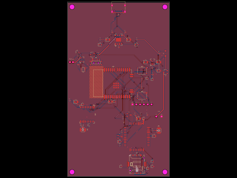 More from this authorpixalynx/esp32-gps-cellular-trackerThis code defines a hardware layout comprising a Wi-Fi-enabled ESP32 module, GPS module, cellular GSM module, battery management components (including charger, protection circuits, and voltage regulators), USB-C connector, SIM card holder, RF components, and supporting passive components for a comprehensive GPS+Cellular tracker device.
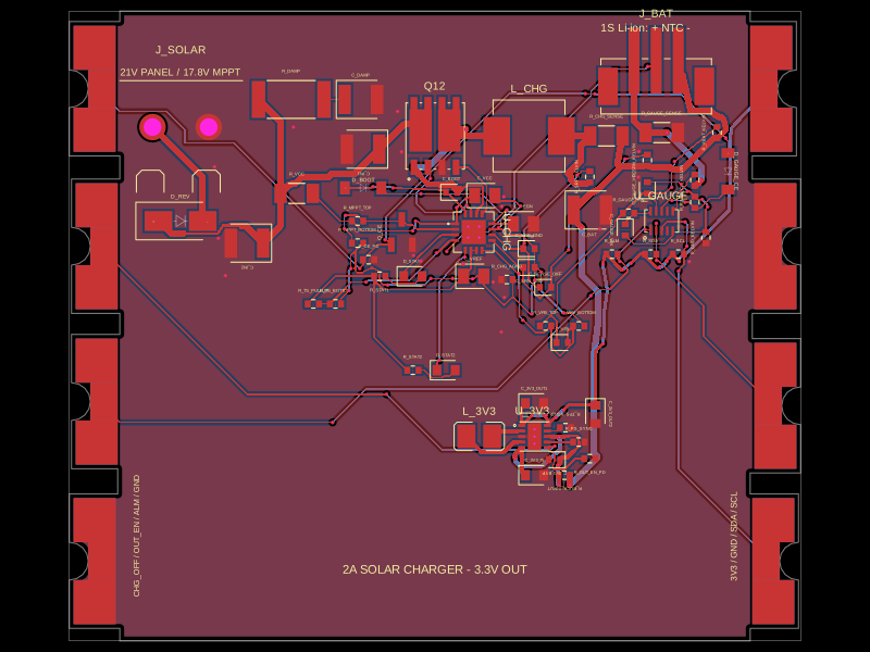 Similar packageShiboSoftwareDev/solar-battery-charger-moduleThis hardware setup integrates a solar panel, a lithium-ion battery, and a multi-rail buck converter with a battery charging IC, protection circuitry, and monitoring components, enabling solar power harvesting, battery charging, and power distribution in an embedded system.
 Discover something newimrishabh18/fitness_watchThis circuit integrates an ESP-12E microcontroller with various sensors and peripherals, including a AO3400A MOSFET for switching loads, to enable wireless control and sensor data processing.