pixalynx/pixal-gps
These files define two separate printed circuit boards: a small, two-layer battery cartridge with protection circuitry and contact pads for a pouch cell, and a larger, two-layer wireless charging dock featuring USB-C input, a resonant coil, and wireless power transmission components.
- Version
- 0.1.2
- License
- unset
- Stars
- 0
docs/wireless-charging.md
# Wireless charging: Qi BPP receiver in the tracker, transmitter in the dock

## Choice

| Role | Part | Why |
| --- | --- | --- |
| Receiver (PCB A) | **TI BQ51013BRHLR**, VQFN-20 3.5 × 4.5 mm, JLC C55663 (1,498 in stock) | the only Qi-BPP receiver found that is a JLCPCB-assemblable QFN, hardware-configured (no I²C/firmware), WPC v1.2 compliant with FOD, and outputs a fixed 5.0 V (4.95–5.04 V) at up to 1.5 A into the nPM1300's 4.0–5.5 V VBUS window (OVP 5.5 V). BQ51013C (WPC 1.3, C43043533) is a drop-in successor. |
| Transmitter (PCB C) | **Injoinic IP6829_MAG_L05_WFNRG**, QFN32 5 × 5 mm, JLC C42411075 (700–2,000 in stock, ≈ $0.95) | single-chip WPC v1.3.3 BPP transmitter with integrated full-bridge FETs, 5 V-in/5 W-out mode, dynamic-power-management for weak USB supplies, FOD, NTC and LED outputs; needs no MCU or firmware work. Every Western single-chip 5 V transmitter (NXP NXQ1TXH5, TI bq500212A/bq500511A, Renesas P9235A) is NRND/obsolete or not stocked. |
| Receiver coil | TDK **WR303050-15F5-G** (12.3 µH, 410 mΩ, 30 × 29.6 × 1.0 mm, ferrite backed, Digi-Key $3.37) or Würth 760308102213 (7.9 µH, 29 × 29 × 0.6 mm) | fits behind a 30 × 40 mm cartridge; Ls in the 8–15 µH range keeps C1 near the BQ51013B reference value |
| Transmitter coil | Vishay **IWTX50R0CZEB6R3KF1** (6.3 µH, 36–45 mΩ, Ø50 × 3 mm, Q 120, "Compliant to Qi standard A11", JLC C6644500) or CND-tek YX-A11-R500800-R0845 (6.3 µH ±5 %, 75 mΩ, Ø50 ferrite, JLC C424425, $0.44) | WPC A11 reference: L 6.3 µH ±10 %, C 400 nF ±5 %, 5 V bridge, 110–205 kHz |

Qi rather than a proprietary link because the size penalty is nil (the BQ51013B plus ~20 passives occupies ≈ 60 mm² of the bottom side), it makes the tracker chargeable on any phone-class pad (a BPP receiver on an EPP pad still gets 5 V/5 W), and the dock becomes optional. Power: 1–3 W is plenty; the receiver's ILIM resistor is set for 1 A so it is never the limiting element (the nPM1300 is, at whatever `VBUSINILIM0` firmware programs, ≤ 800 mA for a 5 W BPP contract).

## Receiver circuit (BQ51013B datasheet §9 / EVM SLUUA44A values)

```
coil ── C36 100 nF ∥ C37 56 nF (C1 series resonant, 50 V X7R) ── AC1
coil ─────────────────────────────────────────────────────────── AC2
C38 2.2 nF C0G across AC1–AC2 (C2 detection)          BOOT1/2: C30/C33 10 nF to AC1/AC2
CLAMP1/2: C31/C34 470 nF to AC1/AC2                   COMM1/2: C32/C35 22 nF to AC1/AC2 (capacitive modulation)
RECT: C39, C40 10 µF 25 V X7R + C41 100 nF            OUT: C42 10 µF + C43 100 nF → VBUS_QI → nPM1300 VBUS
ILIM: R12 68 Ω + R13 200 Ω (RFOD) → 268 Ω ≈ 1 A;  ROS R14 20 kΩ RECT→FOD (TI defaults; calibrate with the FOD tool)

Placement note (Rev A): the receiver's left column faces its BOOT/CLAMP/COMM capacitors, so the RECT capacitors sit
5–8 mm away (C39/C40 10 µF on L4 below the PMIC, C41 100 nF at the far left). TI wants C_RECT close to the pin; for a
1 A, 100–200 kHz rectifier this is tolerable on a prototype, but Rev B should turn the receiver 90° so RECT/OUT face a
free edge and the 10 µF + 100 nF pair sits within 2 mm of the land.
TS: R15 10 kΩ to PGND (no thermistor);  AD → PGND, AD-EN floating (wireless-only)
EN1 = EN2 → nRF9151 P0.01 (high = disable + EPT "charge complete");  CHG → P0.02 with 100 kΩ pull-up (on-pad indication)
```

Resonant values: C1 = 1/((2π·100 kHz)²·Ls') with Ls' the coil inductance measured in the final stack (LiPo and ferrite behind the coil); for Ls' ≈ 16 µH, C1 = 158 nF → 100 nF + 56 nF = 156 nF fitted. C2 = 1/((2π·1 MHz)²·Ls − 1/C1) ≈ 2.1 nF → 2.2 nF C0G. **Measure Ls' on the assembled tracker before the second build**: TI's example coils drop from 11 µH free-space to 16 µH with a battery behind them, and the FOD calibration (RFOD/ROS) must be done with the real enclosure, cartridge and coil, or a Qi pad will refuse the tracker as a "foreign object".

Coil placement: on the rear shell behind the battery cartridge, ferrite side toward the battery (0.3–0.6 mm sintered or flexible ferrite, e.g. Würth WE-FSFS 354), copper side toward the dock. Two 1.8 mm solder pads at the tracker's top edge (P5 COIL1, P6 AC2) take the coil leads; keep the leads short and twisted. The coil's 110–205 kHz field is far from every LTE/GNSS band; the risks are metal-mass detuning of an antenna placed next to the coil (keep both antennas on the opposite end of the enclosure) and LTE bursts coupling into the receiver's mV-level FOD/COMM lines, which is why those parts sit under the ground plane on the bottom side.

## Dock circuit (IP6829 datasheet V1.10 Figure 14 / BOM table)

USB-C 5 V → C1 10 µF + C2/C3 22 µF + C4 100 nF → VIN. CC1/CC2 and D+/D− go straight to the IP6829 (it performs PD/QC requests itself; with a plain 5 V/1 A supply it runs in 5 W mode and uses DPM if the supply sags). Power stage: BST1–LX1 100 nF, BST2–LX2 100 nF, LX1 → 4 × 100 nF C0G 100 V 1206 (= 400 nF ±5 %) → coil → LX2. Current sense: PGND/EPAD → R3 20 mΩ 1 % 0805 → GND with 0 Ω Kelvin links to ISENSE/IGND. Demodulation: coil node → D1 1N5819WS → R4 3.3 kΩ → node (R5 33 kΩ, C9 15 nF to GND) → C10 15 nF → V_DECODE; coil node → R6 100 kΩ → VDET (R7 10 kΩ, C5 2.2 nF to GND). NTC parked with R9 100 kΩ (+ C15 15 nF), LOSS_THR R8 100 kΩ (standard dynamic-FOD sensitivity), LED1/LED2 through 1 kΩ (power/charging and fault per the datasheet table). HOSCI/HOSCO, DEBUG, IO4, IO7 and LED3 are left open as in the reference.

Board: 56 × 44 mm, 2 layers, the A11 coil (Ø50 mm, ferrite-backed) glued above the PCB with its ferrite toward the board; 4 × M2.5 holes. Alignment: the tracker's rear shell and the dock top get a matching recess (≥ 2 mm lip) so the coil centres align within ±3 mm; optional ring magnets are compatible with the IP6829 (the datasheet lists A11/A11a/MP-A2 coils; MP-A2 is the magnet-aligned variant).

Open item recorded from sourcing: the LCSC listing of the sister part IP6826 says "Need to burn firmware"; the IP6829_MAG_L05_WFNRG listing carries no such note, but the first reel must be verified on the bench (or Injoinic asked for the pre-programmed orderable) before a production order.
Related Packages
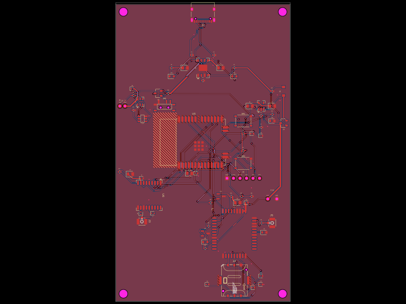 More from this authorpixalynx/esp32-gps-cellular-trackerThis code defines a hardware layout comprising a Wi-Fi-enabled ESP32 module, GPS module, cellular GSM module, battery management components (including charger, protection circuits, and voltage regulators), USB-C connector, SIM card holder, RF components, and supporting passive components for a comprehensive GPS+Cellular tracker device.
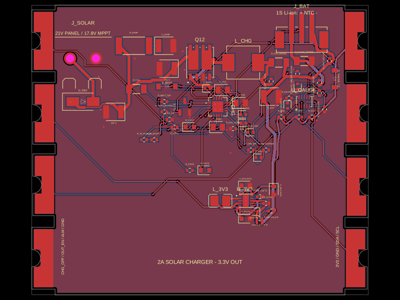 Similar packageShiboSoftwareDev/solar-battery-charger-moduleThis hardware setup integrates a solar panel, a lithium-ion battery, and a multi-rail buck converter with a battery charging IC, protection circuitry, and monitoring components, enabling solar power harvesting, battery charging, and power distribution in an embedded system.
 Discover something newimrishabh18/fitness_watchThis circuit integrates an ESP-12E microcontroller with various sensors and peripherals, including a AO3400A MOSFET for switching loads, to enable wireless control and sensor data processing.