pixalynx/pixal-gps
These files define two separate printed circuit boards: a small, two-layer battery cartridge with protection circuitry and contact pads for a pouch cell, and a larger, two-layer wireless charging dock featuring USB-C input, a resonant coil, and wireless power transmission components.
- Version
- 0.1.2
- License
- unset
- Stars
- 0
docs/firmware-pinmap.md
# nRF9151 pin map for firmware (Zephyr / nRF Connect SDK devicetree)

All application GPIOs are on port 0 and run at VDD_GPIO = 1.8 V (nPM1300 BUCK1).

| Signal | nRF9151 pin | SiP land | Direction | Devicetree hint |
| --- | --- | --- | --- | --- |
| I2C SDA (nPM1300 0x6B, LIS2DW12 0x18) | P0.28 | 47 | open-drain, 10 kΩ pull-ups to 1.8 V | `i2c2` (TWIM), 400 kHz |
| I2C SCL | P0.29 | 48 | | |
| PMIC_INT (nPM1300 GPIO0, mode 5 = IRQ output) | P0.30 | 49 | input, pull-down in the PMIC | `npm1300` `host-int-gpios` |
| ACC_INT1 (LIS2DW12 wake-up) | P0.31 | 50 | input, wake source | `st,lis2dw12` `int1-gpios`, Kconfig `LIS2DW12_TRIGGER`, `WAKEUP` |
| ACC_INT2 | P0.00 | 56 | input (spare interrupt) | `int2-gpios` |
| QI_EN (BQ51013B EN1+EN2; high = stop wireless power, send EPT charge-complete) | P0.01 | 57 | output, default low (internal 200 kΩ pull-downs in the receiver) | gpio |
| QI_CHG (BQ51013B CHG open-drain, 100 kΩ pull-up to 1.8 V; low while the receiver output is enabled = on a pad) | P0.02 | 58 | input | gpio, active-low |
| UART TX (console) | P0.26 | 44 | output, pogo pad TP6 | `uart0` |
| UART RX | P0.27 | 45 | input, pogo pad TP7 | |
| BAT_ID sense | P0.13 / AIN0 | 73 | analog, 100 kΩ series | `adc` channel 0, 10-bit, 40 µs acquisition |
| BAT_ID pull-up drive | P0.14 | 74 | output, high only during the measurement | gpio |
| COEX0 → GNSS LNA enable | COEX0 | 52 | modem-controlled | `AT%XCOEX0=1,1,1565,1586` |
| SWDCLK / SWDIO | 3 / 4 | | TP2 / TP1 | |
| nRESET | 9 | | TP3 through 1 kΩ | |

Unused: P0.03–P0.12, P0.15–P0.25 (P0.21–P0.25 are the ETM trace port; Nordic recommends reserving them — none are routed to pads on Rev A, a Rev B may add a 1.27 mm trace header footprint), MAGPIO0–2, COEX1/2, SDATA/SCLK/VIO.

## nPM1300 configuration written at boot (over I2C)

1. `VBUSINILIM0 = 500 mA` (or up to 800 mA) then `TASKUPDATEILIMSW` — repeat on every `EVENTVBUSDETECTED` (limit reverts to 100 mA on re-dock).
2. `BCHGISETMSB/LSB` = 300 mA, `BCHGVTERM` = 4.20 V, `BCHGITERMSEL` = 10 %, `ADCNTCRSEL = 10K`, `BCHGENABLESET`.
3. `IBATLIM` High (1 A) — mandatory before the modem transmits.
4. BUCK1 stays resistor-configured (1.8 V); LDO1 = load switch (`LDSW1` on only when an active GNSS antenna bias is needed).
5. LED1 = CHARGING (default), LED2 = HOST; GPIO0 mode = GPOIRQ; enable the events you want (VBUS detected/removed, charger status, SHPHLD press/release for the button).
6. Ship mode: `TASKENTERSHIPMODE` after the VBUS-removed event; the SW1 button (SHPHLD, ≥ 96 ms) wakes the system; a 10 s press power-cycles everything.

## Modem AT sequence relevant to this hardware

- `AT%XCOEX0=1,1,1565,1586` — COEX0 high during GNSS in 1565–1586 MHz: powers the SKY65943-11.
- `AT%XANTCFG=1` only when R6 is fitted and the single shared antenna is used (ANT → AUX → LNA).
- Bands: leave `%XBANDLOCK` open; the external antenna choice decides real coverage.
- `AT+CPSMS`, `AT+CEDRXS` for PSM/eDRX; the LFXO is internal, nothing to configure.

## Motion wake-up policy (LIS2DW12)

Low-power mode 1, ODR 12.5 Hz (≈ 1 µA), wake-up threshold ~ 250 mg for 2 samples on INT1 (`WAKE_UP_THS`, `WAKE_UP_DUR`, `CTRL4_INT1_PAD_CTRL.INT1_WU`), no-motion timeout in firmware. On INT1: GNSS fix (A-GPS assisted), one LTE-M report, back to PSM. When stationary for N minutes: skip GNSS, send a heartbeat every eDRX/TAU cycle.
Related Packages
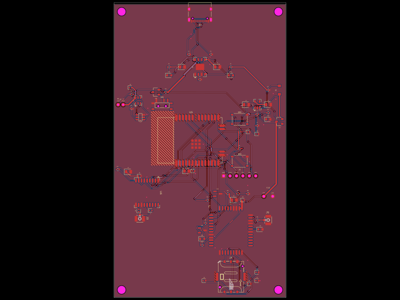 More from this authorpixalynx/esp32-gps-cellular-trackerThis code defines a hardware layout comprising a Wi-Fi-enabled ESP32 module, GPS module, cellular GSM module, battery management components (including charger, protection circuits, and voltage regulators), USB-C connector, SIM card holder, RF components, and supporting passive components for a comprehensive GPS+Cellular tracker device.
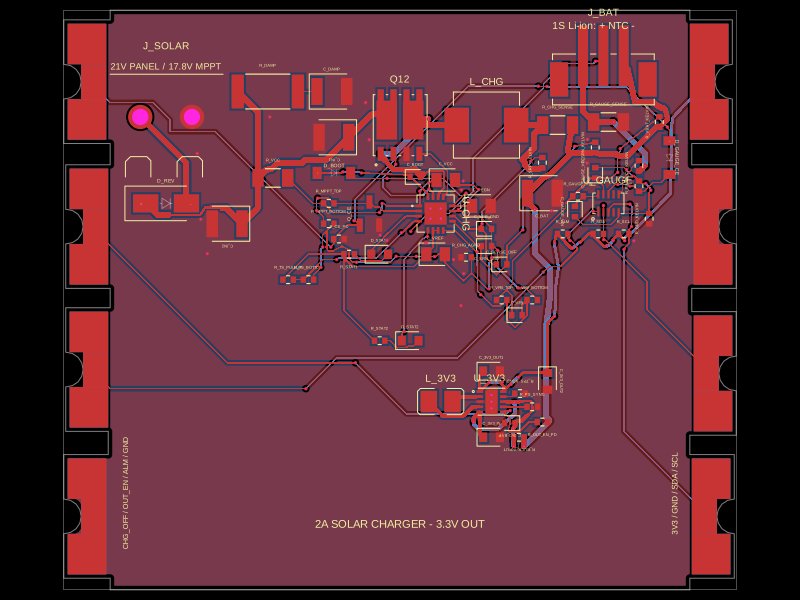 Similar packageShiboSoftwareDev/solar-battery-charger-moduleThis hardware setup integrates a solar panel, a lithium-ion battery, and a multi-rail buck converter with a battery charging IC, protection circuitry, and monitoring components, enabling solar power harvesting, battery charging, and power distribution in an embedded system.
 Discover something newimrishabh18/fitness_watchThis circuit integrates an ESP-12E microcontroller with various sensors and peripherals, including a AO3400A MOSFET for switching loads, to enable wireless control and sensor data processing.