mukesh-dev-git/555-led-blinker
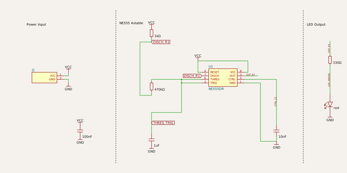
A 36×24 mm NE555-based astable LED blinker accepting 5–12 V through a 2-pin header, with timing RC components, red 1.5 Hz LED output, decoupling, and four M3 mounting holes.
- Version
- 1.0.2
- License
- MIT
- Stars
- 0
index.circuit.tsx
PCB
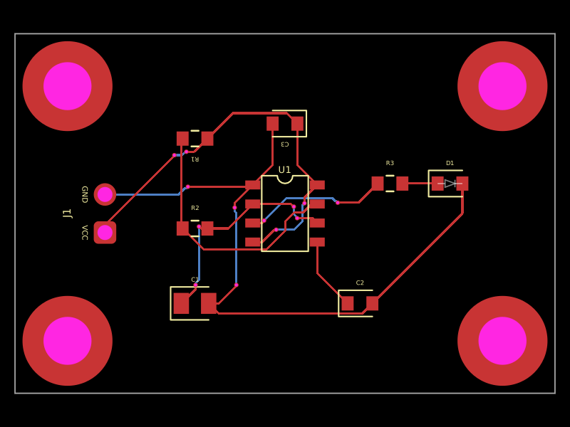
Schematic
// NE555 astable LED blinker, powered from a 2-pin header (5-12 V), with
// four plated M3 mounting holes.
// f = 1.44 / ((R1 + 2 * R2) * C1) = 1.44 / ((1k + 940k) * 1uF) ~ 1.5 Hz
export default () => (
  <board width="36mm" height="24mm">
    <schematicsection name="Power" displayName="Power Input" />
    <schematicsection name="Timer" displayName="NE555 Astable" />
    <schematicsection name="Led" displayName="LED Output" />
    <pinheader
      name="J1"
      schSectionName="Power"
      pinCount={2}
      pitch="2.54mm"
      footprint="pinrow2_p2.54mm_rounded0.3mm"
      pinLabels={["VCC", "GND"]}
      pcbX={-12}
      pcbY={0}
      pcbRotation={90}
      schX={-10}
      schY={0}
    />
    <chip
      name="U1"
      schSectionName="Timer"
      manufacturerPartNumber="NE555DR"
      footprint="soic8"
      pinLabels={{
        pin1: "GND",
        pin2: "TRIG",
        pin3: "OUT",
        pin4: "RESET",
        pin5: "CTRL",
        pin6: "THRES",
        pin7: "DISCH",
        pin8: "VCC",
      }}
      pinAttributes={{
        VCC: { requiresPower: true },
        GND: { requiresGround: true },
        RESET: { mustBeConnected: true },
        TRIG: { mustBeConnected: true },
        THRES: { mustBeConnected: true },
      }}
      schPinArrangement={{
        leftSide: { direction: "top-to-bottom", pins: ["RESET", "DISCH", "THRES", "TRIG"] },
        rightSide: { direction: "top-to-bottom", pins: ["VCC", "OUT", "CTRL", "GND"] },
      }}
      pcbX={0}
      pcbY={0}
      schX={0}
      schY={0}
    />
    <capacitor
      name="C3"
      schSectionName="Power"
      capacitance="100nF"
      footprint="0603"
      pcbX={0}
      pcbY={6}
      pcbRotation={180}
      schX={-8}
      schY={-3}
      schRotation={-90}
    />
    <resistor
      name="R1"
      schSectionName="Timer"
      resistance="1k"
      footprint="0603"
      pcbX={-6}
      pcbY={5}
      pcbRotation={180}
      schX={-4}
      schY={2.5}
      schRotation={-90}
    />
    <resistor
      name="R2"
      schSectionName="Timer"
      resistance="470k"
      footprint="0603"
      pcbX={-6}
      pcbY={-1}
      schX={-4}
      schY={-0.5}
      schRotation={90}
    />
    <capacitor
      name="C1"
      schSectionName="Timer"
      capacitance="1uF"
      footprint="0805"
      pcbX={-6}
      pcbY={-6}
      schX={-4}
      schY={-3.5}
      schRotation={-90}
    />
    <capacitor
      name="C2"
      schSectionName="Timer"
      capacitance="10nF"
      footprint="0603"
      pcbX={5}
      pcbY={-6}
      schX={3}
      schY={-3}
      schRotation={-90}
    />
    <resistor
      name="R3"
      schSectionName="Led"
      resistance="330"
      footprint="0603"
      pcbX={7}
      pcbY={2}
      schX={6}
      schY={1}
      schRotation={-90}
    />
    <led
      name="D1"
      schSectionName="Led"
      color="red"
      footprint="0603"
      supplierPartNumbers={{ jlcpcb: ["C2286"] }}
      pcbX={11}
      pcbY={2}
      schX={6}
      schY={-1.5}
      schRotation={-90}
    />

    <platedhole
      name="MH1"
      pcbX={-14.5}
      pcbY={8.5}
      shape="circle"
      holeDiameter="3.2mm"
      outerDiameter="6mm"
    />
    <platedhole
      name="MH2"
      pcbX={14.5}
      pcbY={8.5}
      shape="circle"
      holeDiameter="3.2mm"
      outerDiameter="6mm"
    />
    <platedhole
      name="MH3"
      pcbX={-14.5}
      pcbY={-8.5}
      shape="circle"
      holeDiameter="3.2mm"
      outerDiameter="6mm"
    />
    <platedhole
      name="MH4"
      pcbX={14.5}
      pcbY={-8.5}
      shape="circle"
      holeDiameter="3.2mm"
      outerDiameter="6mm"
    />

    <trace from=".J1 > .VCC" to="net.VCC" />
    <trace from=".J1 > .GND" to="net.GND" />
    <trace from=".U1 > .VCC" to="net.VCC" />
    <trace from=".U1 > .RESET" to="net.VCC" />
    <trace from=".U1 > .GND" to="net.GND" />
    <trace from=".C3 > .pin1" to="net.VCC" />
    <trace from=".C3 > .pin2" to="net.GND" />

    <trace from=".R1 > .pin1" to="net.VCC" />
    <trace name="DISCH_R1" from=".R1 > .pin2" to=".U1 > .DISCH" />
    <trace name="DISCH_R2" from=".R2 > .pin1" to=".U1 > .DISCH" />
    <trace name="THRES_R2" from=".R2 > .pin2" to=".U1 > .THRES" />
    <trace name="THRES_TRIG" from=".U1 > .THRES" to=".U1 > .TRIG" />
    <trace name="TRIG_C1" from=".C1 > .pin1" to=".U1 > .TRIG" />
    <trace from=".C1 > .pin2" to="net.GND" />
    <trace name="CTRL_C2" from=".C2 > .pin1" to=".U1 > .CTRL" />
    <trace from=".C2 > .pin2" to="net.GND" />

    <trace name="OUT_R3" from=".U1 > .OUT" to=".R3 > .pin1" />
    <trace name="LED_ANODE" from=".R3 > .pin2" to=".D1 > .anode" />
    <trace from=".D1 > .cathode" to="net.GND" />
  </board>
)