mohan-bee/relay-module
A tscircuit package created by mohan-bee.
- Version
- 1.0.0
- License
- unset
- Stars
- 0
mechanical.svg
<svg xmlns="http://www.w3.org/2000/svg" width="1280" height="900" viewBox="0 0 1280 900" role="img" aria-labelledby="title desc">
  <title id="title">NOMINAL RECONSTRUCTION — NOT MEASURED</title>
  <desc id="desc">Nominal 50 by 38 millimeter relay board with four 3 millimeter mounting holes at plus or minus 22 by plus or minus 16 millimeters from its center. Hole spacing is 44 by 32 millimeters, leaving 3 millimeter center-to-edge offsets. All module geometry is unverified.</desc>
  <defs>
    <marker id="arrow-start" markerWidth="8" markerHeight="8" refX="0" refY="3.5" orient="auto" markerUnits="strokeWidth"><path d="M7 0L0 3.5L7 7Z" fill="#445363"/></marker>
    <marker id="arrow-end" markerWidth="8" markerHeight="8" refX="7" refY="3.5" orient="auto" markerUnits="strokeWidth"><path d="M0 0L7 3.5L0 7Z" fill="#445363"/></marker>
    <style>
      text { font-family: Arial, Helvetica, sans-serif; fill: #172b40; }
      .outline { fill: none; stroke: #172b40; stroke-width: 3; }
      .hole { fill: white; stroke: #172b40; stroke-width: 2.5; }
      .ext { fill: none; stroke: #9ba7b1; stroke-width: 1.3; }
      .dim { fill: none; stroke: #445363; stroke-width: 1.5; marker-start: url(#arrow-start); marker-end: url(#arrow-end); }
      .center { fill: none; stroke: #9ba7b1; stroke-width: 1.2; stroke-dasharray: 12 5 2 5; }
      .label { font-size: 24px; text-anchor: middle; }
      .small { font-size: 18px; fill: #526272; }
      .coord { font-size: 18px; fill: #526272; }
    </style>
  </defs>
  <rect width="1280" height="900" fill="white"/>
  <text x="64" y="53" font-size="29" font-weight="700">NOMINAL RECONSTRUCTION — NOT MEASURED</text>
  <text x="64" y="88" font-size="20" fill="#526272">HL-52S V1.0 · mechanical reference · all dimensions in mm</text>
  <line x1="64" y1="110" x2="1216" y2="110" stroke="#d3d9de"/>

  <!-- Nominal PCB: 13 drawing pixels per millimeter. -->
  <rect class="outline" x="300" y="230" width="650" height="494"/>
  <path class="center" d="M280 477H970M625 210V744"/>
  <g class="hole">
    <circle cx="339" cy="269" r="19.5"/>
    <circle cx="911" cy="269" r="19.5"/>
    <circle cx="339" cy="685" r="19.5"/>
    <circle cx="911" cy="685" r="19.5"/>
  </g>
  <g class="center">
    <path d="M308 269H370M339 238V300M880 269H942M911 238V300"/>
    <path d="M308 685H370M339 654V716M880 685H942M911 654V716"/>
  </g>

  <!-- Board outside dimensions. -->
  <path class="ext" d="M300 223V138M950 223V138M293 230H192M293 724H192"/>
  <path class="dim" d="M300 150H950"/>
  <path class="dim" d="M207 230V724"/>
  <text class="label" x="625" y="140">50</text>
  <text class="label" x="185" y="477" transform="rotate(-90 185 477)">38</text>

  <!-- Hole center dimensions. -->
  <path class="ext" d="M339 238V183M911 238V183M942 269H1033M942 685H1033"/>
  <path class="dim" d="M339 195H911"/>
  <path class="dim" d="M1018 269V685"/>
  <text class="label" x="625" y="185">44</text>
  <text class="label" x="1049" y="477" transform="rotate(-90 1049 477)">32</text>

  <!-- Center-to-edge offsets. -->
  <path class="ext" d="M300 731V785M339 716V785M293 230H247M308 269H247"/>
  <path class="dim" d="M300 772H339"/>
  <path class="dim" d="M260 230V269"/>
  <text class="label" x="319.5" y="761">3</text>
  <text class="label" x="239" y="257">3</text>
  <text class="small" x="380" y="777">Hole-center edge offset: 3, all four sides</text>

  <path d="M925 254L1073 217H1185" fill="none" stroke="#445363" stroke-width="1.5"/>
  <text x="1081" y="204" font-size="24">4 × Ø3</text>
  <text class="small" x="1070" y="244">Mounting holes</text>

  <text class="coord" x="376" y="313">(−22, +16)</text>
  <text class="coord" x="871" y="313" text-anchor="end">(+22, +16)</text>
  <text class="coord" x="376" y="651">(−22, −16)</text>
  <text class="coord" x="871" y="651" text-anchor="end">(+22, −16)</text>
  <text x="625" y="382" font-size="23" font-weight="700" text-anchor="middle">TOP VIEW</text>
  <text class="small" x="625" y="411" text-anchor="middle">Origin at board center</text>
  <path d="M625 477V427" fill="none" stroke="#445363" stroke-width="1.7" marker-end="url(#arrow-end)"/>
  <path d="M625 477H705" fill="none" stroke="#445363" stroke-width="1.7" marker-end="url(#arrow-end)"/>
  <circle cx="625" cy="477" r="3.5" fill="#172b40"/>
  <text class="small" x="714" y="483">+X</text>
  <text class="small" x="638" y="428">+Y</text>
  <text class="small" x="625" y="554" text-anchor="middle">Nominal PCB thickness: 1.6</text>
  <text class="small" x="625" y="582" text-anchor="middle">Terminals left · headers right</text>

  <line x1="64" y1="813" x2="1216" y2="813" stroke="#d3d9de"/>
  <text x="64" y="844" font-size="19">Imported component pitches: input / supply headers 2.54; screw terminals 5.00.</text>
  <text class="small" x="64" y="875">Board and hole geometry are unverified. Measure a physical sample before mechanical use.</text>
</svg>
Related Packages
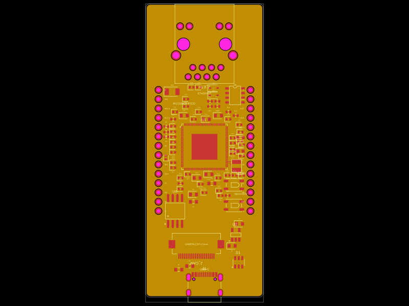 More from this authormohan-bee/RV1106G2This code defines a detailed hardware schematic with schematic symbols, footprints, and 3D models for various electronic components including microcontrollers, voltage regulators, connectors, and passive parts, designed for PCB layout and routing.
 Discover something newgokul/cm4-media-carrier