mohan-bee/infrared-battle-tag
A compact board featuring an ATtiny1616 microcontroller, tactile switch, and MMBT2222A transistor, with VCC/GND power and the switch connected to the MCU’s PA4 input.
- Version
- 1.0.2
- License
- unset
- Stars
- 0
index.circuit.tsx
PCB

Schematic

import { Fragment } from "react"
import { ATTINY1616_SN } from "./imports/ATTINY1616_SN"
import { TSOP38238 } from "./imports/TSOP38238"
import { TSAL6200 } from "./imports/TSAL6200"
import { MMBT2222ALT1G } from "./imports/MMBT2222ALT1G"
import { A_1N5819WS } from "./imports/A_1N5819WS"
import { TS_1102S_C_C_B } from "./imports/TS_1102S_C_C_B"

// Two identical boards. External switched 3xAAA holder, 3.3–4.8 V input.
// PA4 generates the 38 kHz carrier. RESET_GAME is a GPIO, not UPDI/reset.
export default function BattleTag() {
  return (
    <board width="60mm" height="45mm" layers={2} autorouter="auto-local"
      minTraceWidth="0.25mm" pcbStyle={{ silkscreenFontSize: 0.8 }}>
      <schematicsheet name="Main" displayName="IR battle tag / Rev A" sheetSize="A4" />
      <group name="circuit" schSheetName="Main">
      <net name="GND" isGroundNet />
      <net name="VCC" isPowerNet nominalTraceWidth="0.5mm" />
      <net name="VBAT" isPowerNet nominalTraceWidth="0.5mm" />
      <net name="RX_VCC" isPowerNet />
      {['IR_TX', 'IR_RX', 'FIRE', 'RESET_GAME', 'LIFE1', 'LIFE2', 'LIFE3', 'UPDI'].map(name => <Fragment key={name}><net name={name} /></Fragment>)}

      <schematicsection name="Power" displayName="01 / 3xAAA POWER" />
      <pinheader name="J1" pinCount={2} schX={(-14)*0.6} schY={(8)*0.6} pcbX={-24} pcbY={-14} schSectionName="Power" />
      <A_1N5819WS pcbRotation={180} name="D1" schRotation={-90} schX={(-10)*0.6} schY={(8)*0.6} pcbX={-18} pcbY={-14} schSectionName="Power" />
      <capacitor name="C1" capacitance="47uF" footprint="1210" schX={(-6)*0.6} schY={(7)*0.6} schRotation={-90} pcbX={-13} pcbY={-12} schSectionName="Power" />
      <capacitor name="C2" pcbRotation={180} capacitance="100nF" footprint="0603" schX={(-3)*0.6} schY={(7)*0.6} schRotation={-90} pcbX={-6.5} pcbY={-8} schSectionName="Power" />
      <trace from=".J1 > .pin1" to="net.VBAT" />
      <trace from=".J1 > .pin2" to="net.GND" />
      <trace from="net.VBAT" to=".D1 > .anode" />
      <trace from=".D1 > .cathode" to="net.VCC" />
      <trace from=".C1 > .pin1" to="net.VCC" /><trace from=".C1 > .pin2" to="net.GND" />
      <trace from=".C2 > .pin1" to="net.VCC" /><trace from=".C2 > .pin2" to="net.GND" />

      <schematicsection name="MCU" displayName="02 / CONTROLLER + UPDI" />
      <ATTINY1616_SN name="U1" schX={(5)*0.6} schY={(6)*0.6} schWidth={1.7} schHeight={2.2} pcbX={0} pcbY={0}
        schSectionName="MCU"
        schPinArrangement={{leftSide: [1,16,17,18,19,6,7,8,9,20], rightSide: [2,3,4,5,10,11,12,13,14,15]}}
        noConnect={['pin6','pin7','pin8','pin9','pin12','pin13','pin14','pin15','pin18','pin19']} />
      <pinheader name="J2" pinCount={3} schX={(3)*0.6} schY={(2)*0.6} pcbX={19} pcbY={-15} schSectionName="MCU" />
      <trace from=".U1 > .VDD" to="net.VCC" /><trace from=".U1 > .GND" to="net.GND" />
      <trace from=".U1 > .UPDI" to="net.UPDI" />
      <trace from=".J2 > .pin1" to="net.VCC" /><trace from=".J2 > .pin2" to="net.UPDI" /><trace from=".J2 > .pin3" to="net.GND" />
      <trace from=".U1 > .PA4" to="net.IR_TX" /><trace from=".U1 > .PA1" to="net.IR_RX" />
      <trace from=".U1 > .PA5" to="net.LIFE1" /><trace from=".U1 > .PA6" to="net.LIFE2" /><trace from=".U1 > .PA7" to="net.LIFE3" />
      <trace from=".U1 > .PB1" to="net.FIRE" /><trace from=".U1 > .PB0" to="net.RESET_GAME" />

      <schematicsection name="TX" displayName="03 / 940nm TRANSMITTER" />
      <resistor name="R1" resistance="68" footprint="1206" schX={(21)*0.6} schY={(10)*0.6} schRotation={-90} pcbX={-16} pcbY={12} schSectionName="TX" />
      <TSAL6200 name="LED1" schDisplayValue="TSAL6200" schX={(21)*0.6} schY={(7.5)*0.6} schRotation={-90} pcbX={-20} pcbY={18} schSectionName="TX" />
      <MMBT2222ALT1G name="Q1" schX={(20.8)*0.6} schY={(5)*0.6} pcbX={-15} pcbY={7} schSectionName="TX" />
      <resistor name="R2" pcbRotation={180} resistance="680" footprint="0603" schX={(17)*0.6} schY={(5)*0.6} pcbX={-10} pcbY={7} schSectionName="TX" />
      <resistor name="R3" resistance="100k" footprint="0603" schX={(19)*0.6} schY={(2.5)*0.6} schRotation={-90} pcbX={-15} pcbY={3} schSectionName="TX" />
      <trace from="net.VCC" to=".R1 > .pin1" /><trace from=".R1 > .pin2" to=".LED1 > .anode" />
      <trace from=".LED1 > .cathode" to=".Q1 > .pin3" /><trace from=".Q1 > .pin2" to="net.GND" />
      <trace from="net.IR_TX" to=".R2 > .pin1" /><trace from=".R2 > .pin2" to=".Q1 > .pin1" />
      <trace from=".R3 > .pin1" to=".Q1 > .pin1" /><trace from=".R3 > .pin2" to="net.GND" />

      <schematicsection name="RX" displayName="04 / 38kHz RECEIVER" />
      <resistor name="R4" schRotation={-90} resistance="100" footprint="0603" schX={(19)*0.6} schY={(-2)*0.6} pcbX={17} pcbY={11} schSectionName="RX" />
      <capacitor name="C3" capacitance="4.7uF" footprint="0805" schX={(22)*0.6} schY={(-4)*0.6} schRotation={-90} pcbX={22} pcbY={11} schSectionName="RX" />
      <TSOP38238 name="U2" schX={(18)*0.6} schY={(-6)*0.6} schWidth={1} schHeight={0.4} pcbX={20} pcbY={18}
        schSectionName="RX" schPinArrangement={{leftSide: [3,2], rightSide: [1]}} />
      <trace from="net.VCC" to=".R4 > .pin1" /><trace from=".R4 > .pin2" to="net.RX_VCC" />
      <trace from=".C3 > .pin1" to="net.RX_VCC" /><trace from=".C3 > .pin2" to="net.GND" />
      <trace from=".U2 > .VS" to="net.RX_VCC" /><trace from=".U2 > .GND" to="net.GND" /><trace from=".U2 > .OUT" to="net.IR_RX" />

      <schematicsection name="UI" displayName="05 / LIVES" />
      {[0,1,2].map(i => <Fragment key={i}>
        <resistor name={`R${5+i}`} pcbRotation={i === 0 ? 180 : 0} resistance="1k" footprint="0603" schX={(-12+i*5)*0.6} schY={(-2)*0.6} schRotation={-90} pcbX={-7+i*7} pcbY={11} schSectionName="UI" />
        <led name={`LED${2+i}`} color="red" schDisplayValue="RED" footprint="0805" schX={(-12+i*5)*0.6} schY={(-4.5)*0.6} schRotation={-90} pcbX={-7+i*7} pcbY={16} schSectionName="UI" />
        <trace from={`net.LIFE${i+1}`} to={`.R${5+i} > .pin1`} />
        <trace from={`.R${5+i} > .pin2`} to={`.LED${2+i} > .anode`} />
        <trace from={`.LED${2+i} > .cathode`} to="net.GND" />
      </Fragment>)}
      <TS_1102S_C_C_B name="SW1" schX={-7.87} schY={(-10)*0.6} pcbX={-14} pcbY={-5} schSectionName="UI" />
      <TS_1102S_C_C_B name="SW2" schX={(-3)*0.6} schY={(-10)*0.6} pcbX={14} pcbY={-5} schSectionName="UI" />
      <resistor name="R8" resistance="10k" footprint="0603" schX={(-14)*0.6} schY={(-8)*0.6} schRotation={-90} pcbX={-21} pcbY={0} schSectionName="UI" />
      <resistor name="R9" resistance="10k" footprint="0603" schX={(-6)*0.6} schY={(-8)*0.6} schRotation={-90} pcbX={21} pcbY={0} schSectionName="UI" />
      <trace from=".R8 > .pin1" to="net.VCC" /><trace from=".R8 > .pin2" to="net.FIRE" />
      <trace from=".R9 > .pin1" to="net.VCC" /><trace from=".R9 > .pin2" to="net.RESET_GAME" />
      <trace from=".SW1 > .pin1" to="net.FIRE" /><trace from=".SW1 > .pin3" to="net.GND" />
      <trace from=".SW2 > .pin1" to="net.RESET_GAME" /><trace from=".SW2 > .pin3" to="net.GND" />

      </group>
      {[[-26,-18.5],[26,-18.5],[-26,18.5],[26,18.5]].map(([x,y],i) => <Fragment key={i}><hole name={`H${i+1}`} diameter="2.5mm" pcbX={x} pcbY={y} /></Fragment>)}
      <silkscreentext text="Q1" pcbX={-12.5} pcbY={5.5} fontSize={0.8} />
      <silkscreencircle pcbX={-20} pcbY={18} radius={2.5} />
      <silkscreentext text="IR TX" pcbX={-20} pcbY={21.3} fontSize={0.8} />
      <silkscreentext text="A" pcbX={-21.27} pcbY={16.3} fontSize={0.8} />
      <silkscreentext text="K" pcbX={-18.73} pcbY={16.3} fontSize={0.8} />
      <silkscreentext text="IR BATTLE TAG / REV A" pcbX={0} pcbY={-20} fontSize={1.1} />
      <silkscreentext text="FIRE" pcbX={-17} pcbY={-10} fontSize={1} />
      <silkscreentext text="NEW GAME" pcbX={14} pcbY={-10} fontSize={1} />
      <silkscreentext text="3xAAA + / -" pcbX={-21} pcbY={-17} fontSize={0.8} />
      <silkscreentext text="V / UPDI / G" pcbX={19} pcbY={-18} fontSize={0.8} />
    </board>
  )
}
Related Packages
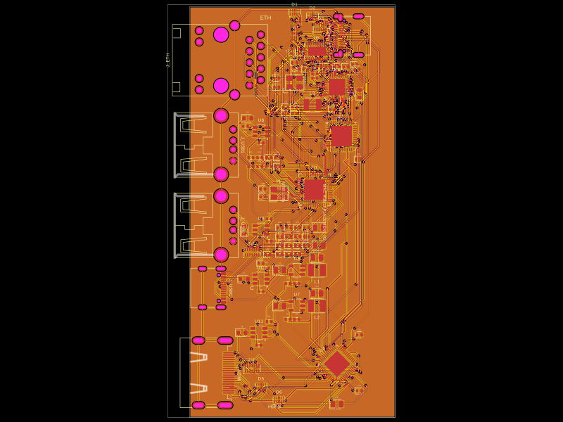 More from this authormohan-bee/hubThis design implements a compact USB-C hub with HDMI output, gigabit Ethernet, multiple USB ports, and integrated power management and ESD protection components.
 Similar packagejettos/powercore16-revc-complete-board-modelThis code defines the hardware layout for a power distribution and control circuit featuring high-current power inputs, multiple output switches with programmable fuses, MCU-based control, input connectors, and communication interfaces, all represented with specific component footprints and connectivity zones.
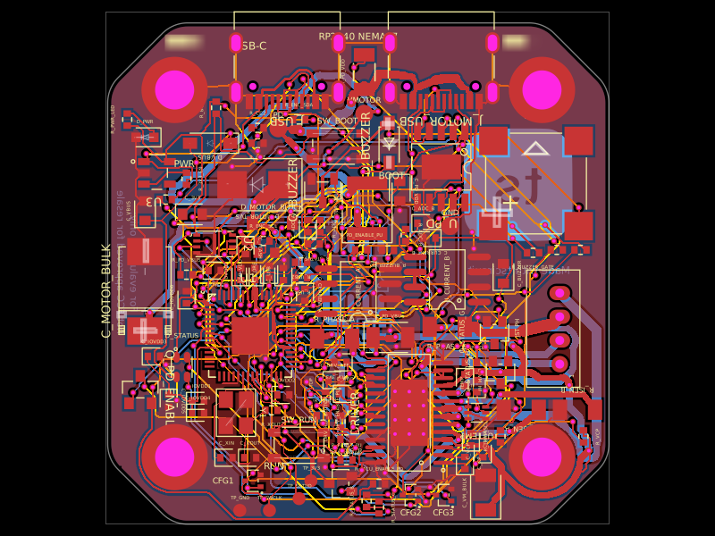 Discover something newimrishabh18/rp2040-motor-controllerA 4-layer RP2040-based NEMA17 stepper-motor controller PCB with USB-C PD power negotiation, DRV8825 dual H-bridge driver, current/temperature sensing, optional encoder, RGB/buzzer status outputs, protection, and programming interfaces.