imrishabh18/rp2040-motor-controller
An RP2040-based NEMA17 stepper-motor controller with USB-C programming and PD motor-power negotiation, DRV8825 dual H-bridge drive, current/temperature telemetry, protected power filtering, status RGB LED, buzzer alarm, and optional magnetic encoder.
- Version
- 1.0.42
- License
- unset
- Stars
- 3
engineering/usb-c-20v-v1.0.38.md
# USB-C replacement, v1.0.38

Both J_MOTOR_USB (PWR) and J_USB (DATA) now use **HRO TYPE-C-31-M-12, JLCPCB C165948**. The [manufacturer drawing](https://datasheet.lcsc.com/datasheet/pdf/9e56b777c022540fcce7c7f67825f55e.pdf?productCode=C165948) specifies **20 V / 5 A**. This replaces the prior C2765186 part's 5 V operating rating; it does not change either port's function or the board's approximately 1 A peak winding-current limit.

## Import and layout

Imported with `tsci import C165948 --jlcpcb --use-exact-footprint`. `imports/TYPE_C_31_M_12.tsx` is the unchanged supplier import. `imports/usb-c-20v.tsx` only remaps pin identifiers to the established schematic numbering; it preserves all supplier footprint geometry and CAD data. The former generic USB footprint and C2765186 wrapper are removed.

The supplier footprint has 12 SMT lands (including four polygon-shaped power/ground lands), four plated shell slots and two 0.6 mm locator holes per connector. Both parts move 0.2 mm toward the board edge. Local traces and through-slot layer transitions have been adjusted, and ground pours regenerated. No ICs, passives or test points were removed.

The imported footprint is the EasyEDA supplier layout, not a claim that its dimensions exactly equal every dimension in the HRO recommended pattern. For example, it uses 0.8 mm-wide shell slots, 1.4/1.6 mm long, where the drawing suggests 0.6 mm-wide, 1.4/1.7 mm slots. The connector stakes shown are 0.8/1.1 mm long in plan view; both fit the imported slots. Locator centres differ by approximately 0.01 mm per side from the drawing, within its stated PCB layout tolerance. The exact imported geometry is retained, rather than silently substituting a generic footprint.

The HRO drawing shows top mounting without the prior part's 0.8 mm PCB restriction. Shell stakes extend about 1.01 mm below the mounting plane. On a 1.6 mm board they terminate within the plated slots: JLCPCB should review solder filling/wetting and component orientation during assembly review. Electrical rating and clean DRC do not prove assembled solder-joint quality.

## Validation

See `revision-checks.json` for the current build hashes and detailed results. Regression checks cover both supplier numbers, physical USB contact order, connector placement, locator holes and plated slots. An independent polygon-aware copper audit checks the imported power lands. The exported Excellon audit verifies all eight shell slots as well as all four locator holes. Existing PD control, Kelvin sensing, outer-layer motor routing, current limits, and the twelve imported driver thermal vias are retained.

The firmware package remains absent. Application software is still required to select the desired PD voltage and operate the motor. Powered hardware validation remains outstanding.
Related Packages
 More from this authorimrishabh18/3d-model-testIt loads a 3D model of an electronic component onto a circuit board with specified positioning.
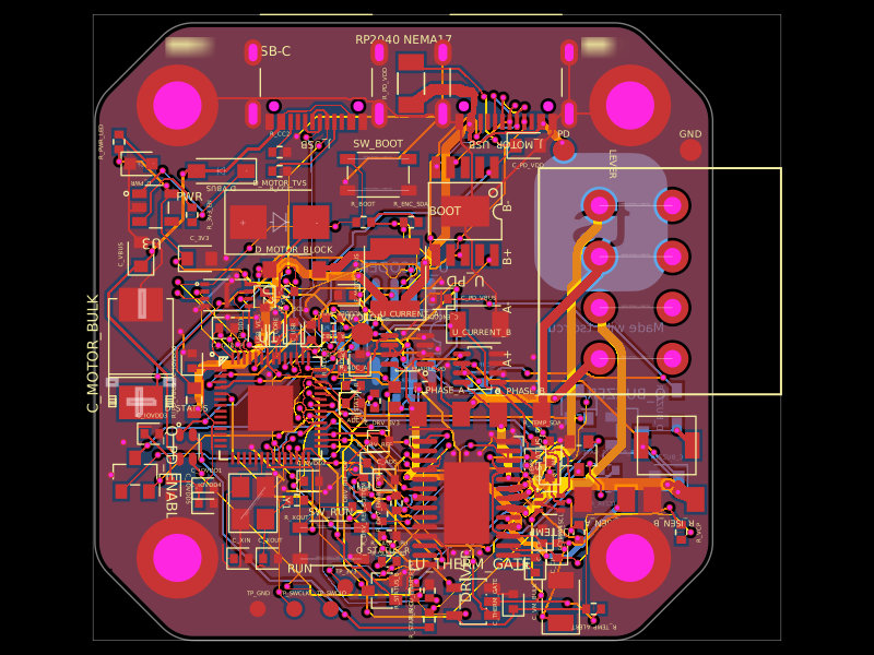 Similar packageastra/nema17-stepper-motor-controller-spring-clamp-rp2040A 4-layer RP2040 controller board that negotiates USB‑C PD motor power and drives a NEMA17 stepper via a DRV8825, with current sensing, thermal shutdown, RGB status LED, buzzer alarm, optional AS5600 encoder, protection/filtering, and test points.
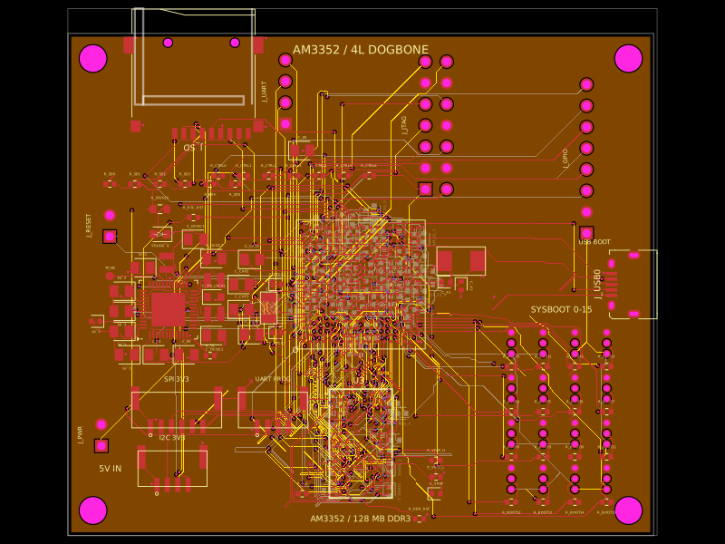 Discover something newseveibar/am3352-dev-board-4layer-dogboneDefines PCB footprints and pin mappings for a TI AM3352ZCZ100 processor, JST GH connectors, and assembly-part lookup helpers for capacitors, resistors, and headers.