imrishabh18/rp2040-motor-controller
An RP2040-based NEMA17 stepper-motor controller with USB-C programming and PD motor-power negotiation, DRV8825 dual H-bridge drive, current/temperature telemetry, protected power filtering, status RGB LED, buzzer alarm, and optional magnetic encoder.
- Version
- 1.0.41
- License
- unset
- Stars
- 3
engineering/final-fabrication-review-v1.0.36.md
# Final fabrication review — v1.0.36

Reviewed 30 September 2026 (Asia/Kolkata). No electrical or layout changes were made during this review.

**Result: static checks pass for a prototype fabrication run.** No shorts, disconnected physical nets, native DRC errors, or new pin-mapping/logic errors were found within the checks below. This is not a powered-hardware qualification. The design retains layout advisories, a roughly 1 A peak winding-current setting, and application-firmware requirements.

## Fresh verification

| Check | Result |
|---|---|
| TypeScript and clean circuit build | Pass |
| Logical netlist | 0 errors, 0 warnings |
| Routed native DRC | 0 errors; 179 warnings classified below |
| Gerber-mode short detection, all four copper layers | 0 shorts |
| Independent physical copper audit | 106 nets checked; 0 short contacts, split nets, or unmapped elements |
| Drill spacing and audited drill-to-copper clearance | 0 violations |
| Ground connectivity | One connected network across all layers; also one using outer layers and plated barrels only |
| Current-sense Kelvin branches | All four remain separate from load-current paths until the shunt pads |
| Motor-current routing | All 11 checked power nets use top/bottom trace segments |
| Imported driver thermal vias | All 12 plated drills present; exposed pad solderable; bottom tented; solid ground contact on all four layers |
| Regression suite | 23 passed, 0 failed, 2,235 assertions |
| Assembly export | Matching BOM/CPL, 103 top components, no bottom population; mounting holes/test pads and optional encoder excluded |

The exact hashes and machine-readable results are in [revision-checks.json](revision-checks.json). Fresh command logs are in the verification archive under `reports/final-review/`. The rebuilt circuit differs from the earlier v1.0.36 export only in supplier-warning IDs/order and build metadata; all electrical and geometric elements match. Fabrication outputs were regenerated from the reviewed build.

## Logic and component review

- **Driver:** physical DRV8825 pins, charge-pump connections, isolated V3P3OUT, reference divider, regulation shunts, STEP/DIR, reset, enable and fault connections agree with the [TI datasheet](https://www.ti.com/lit/ds/symlink/drv8825.pdf). The divider produces nominally 1.5 V; `I_FS = V_REF / (5 × R_SENSE)` with 0.3 Ω shunts gives **1 A peak**. Mode wiring selects 1/16 microsteps and open DECAY selects mixed decay. The requested 1.7 A upgrade was not implemented.
- **PD selection:** CH224K CFG1/2/3 are physical pins **9/2/3**, controlled by GPIO4/5/6 through three inverting DTC114EETL buffers. Pull-ups reference CH224K VDD, keeping its domain separate from MCU 3.3 V. Startup requests 5 V; software can request 9/12/15/20 V. Checked against the CH224K-specific sections of the [WCH CH224 v2.0 datasheet, manufacturer-authored mirror](https://done.land/assets/files/ch224aq_datasheet.pdf) and [ROHM buffer datasheet](https://fscdn.rohm.com/en/products/databook/datasheet/discrete/transistor/digital/dtc114eetl-e.pdf). CH224A/Q tables must not be substituted for the K variant.
- **Enable path:** GPIO22 is pulled low and feeds DRV8825 nSLEEP through the PD-controlled [BSS84](https://www.diodes.com/datasheet/download/BSS84.pdf). Reset/unpowered MCU state leaves the motor asleep. PG is used by this hardware path, not read by a dedicated MCU input. Software must hold GPIO22 low through voltage negotiation and settling.
- **Current telemetry:** both INA240A1DR SOIC pin mappings match the [TI datasheet](https://www.ti.com/lit/ds/symlink/ina240.pdf). REF1 at 3.3 V and REF2 at ground give a nominal 1.65 V offset. Gain 20 and separate 0.05 Ω shunts give 1 V/A, approximately 0.65–2.65 V over ±1 A. Inputs, output filters and MCU ADC assignments were checked; these shunts do not replace the driver's 0.3 Ω regulation shunts.
- **Temperature:** TMP102 supply, address 0x48, GPIO26/27 I²C and pull-ups agree with the [TI datasheet](https://www.ti.com/lit/ds/symlink/tmp102.pdf). ALERT is intentionally unused; R_TEMP_ALERT and the external AND gate are absent. There is no autonomous TMP102 board-temperature cutoff. DRV8825's internal die-temperature shutdown remains.
- **Power and feedback:** reviewed motor-fuse/diode polarity, 50 V motor capacitors, TVS, CH224K feed-resistor power, isolated USB supplies, buzzer switch/flyback and RGB drivers. No firmware is included. DATA USB powers the MCU; motor USB powers the motor section.

## Advisories and fabrication conditions

- **179 warnings remain:** 103 failed online supplier lookups, 19 trace-length advisories, 13 missing courtyards, and 44 pin/refdes/symbol metadata warnings. Supplier footprints are already imported locally; the offline lookup failures did not remove geometry. These checks do not verify live stock or the supplier's current assembly rotation metadata.
- **The 19 length advisories are not all metadata noise.** Examples are the DRV V3P3OUT bypass route (7.23 mm against 4.5 mm guidance), PD VDD bypass route (12.95 mm against 10 mm), and current-sensor bypass branches. Several ground-route lengths are shortened electrically by the connected pours, but no power-integrity simulation or scope measurements were performed. Check rail stability, ADC noise and switching ripple on the prototype.
- **37 reviewed power-to-pad gaps** are below the preferred 0.15 mm rule, all at or above the unchanged 0.10 mm hard rule. Exact pairs and accepted limits remain in [the clearance review](power-pad-clearance-review.json). Do not order 2 oz copper without redesign/revalidation: [JLCPCB's current capability table](https://jlcpcb.com/capabilities/pcb-capabilities) specifies 0.15 mm track spacing for 2 oz multilayer boards. This review assumes the existing four-layer, 1.6 mm design and 1 oz outer copper.
- Eight placement orientation suggestions remain; placement DRC itself has 0 errors and 0 warnings. The suggested passive rotations are routing heuristics, not reversed polarized parts. One schematic box-padding advisory remains.
- Motor power runs are widened, but VMA retains a **0.69 mm-long, 0.15 mm-wide local escape**. Do not infer 1.7 A thermal capability from the routing or the added vias.
- The twelve thermal vias are open within the top exposed-pad mask and tented on the bottom. They are not specified as filled/capped vias. Assembly process and solder coverage under the driver still matter.
- The assembly exporter lacks complete supplier pin-1 metadata. Check the final JLCPCB placement preview for the driver, USB connectors, polarized parts and transistors before approving assembly. This review did not inspect a new JLCPCB order preview or approve an order.

## First-board operating limits

At the default 5 V request, the motor cannot run. DRV8825 requires at least 8.2 V at its supply; account for the fuse/diode drop when selecting a supported PD voltage. Firmware must configure STEP/DIR/reset/enable, select voltage, and implement temperature and fault handling.

Measure startup overshoot, motor-bus ripple/regeneration and temperature at the intended load before extended operation. The motor bus has a reverse-blocking diode and no active discharge/brake; lowering the PD request does not guarantee immediate discharge of stored motor-bus energy. Firmware cannot presently measure that rail directly. Confirm transitions with the labelled test pads during bring-up. The nearby TMP102 also lags driver die temperature.

The optional bottom AS5600 is intentionally unpopulated. Mechanical fit to the motor, spacers, shaft/magnet and connector leads remains a physical fit check.

Publication is verified separately by comparing registry files against this source and these fabrication outputs. The publication receipt records the actual remote version and preview-build status.
Related Packages
 More from this authorimrishabh18/3d-model-testIt loads a 3D model of an electronic component onto a circuit board with specified positioning.
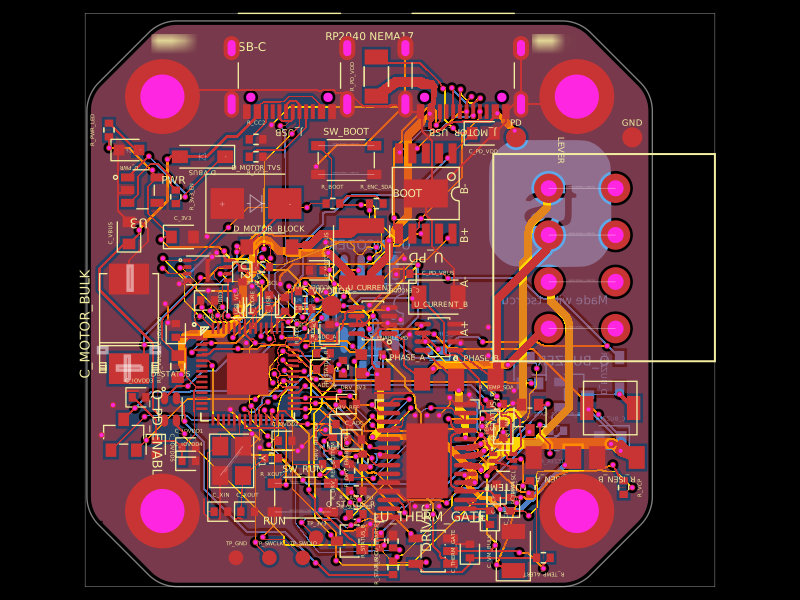 Similar packageastra/nema17-stepper-motor-controller-spring-clamp-rp2040A 4-layer RP2040 controller board that negotiates USB‑C PD motor power and drives a NEMA17 stepper via a DRV8825, with current sensing, thermal shutdown, RGB status LED, buzzer alarm, optional AS5600 encoder, protection/filtering, and test points.
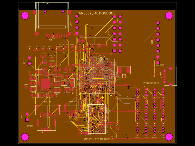 Discover something newseveibar/am3352-dev-board-4layer-dogboneDefines PCB footprints and pin mappings for a TI AM3352ZCZ100 processor, JST GH connectors, and assembly-part lookup helpers for capacitors, resistors, and headers.