imrishabh18/rp2040-motor-controller
An RP2040-based NEMA17 stepper-motor controller with USB-C programming and PD motor-power negotiation, DRV8825 dual H-bridge drive, current/temperature telemetry, protected power filtering, status RGB LED, buzzer alarm, and optional magnetic encoder.
- Version
- 1.0.41
- License
- unset
- Stars
- 3
engineering/drv8825-thermal-vias.md
# DRV8825 thermal-via correction — local v1.0.30

The published v1.0.29 had six ground vias beyond the exposed-pad ends and none
inside the pad. This revision adds ten plated through vias directly in the
3.1 × 5.6 mm exposed pad: 0.30 mm finished-hole design diameter and 0.50 mm
copper-pad diameter. The six existing perimeter vias remain.

The ten via centers (board coordinates, millimeters) are a 3 × 3 array at
x = 3.3, 4.5, 5.3 and y = −12.5, −11.5, −10.5, plus (5.3, −13.2).
Their positions avoid existing signal and power copper on every layer. All
266 saved routes and every existing component/pad position are unchanged.

Two bounded ground pours under the driver add local heat spreading on inner1
and inner2. Existing routes cut these into three physical regions; all three
join the same ground network through the thermal vias. The vias have solid
connections around their full circumference to the top exposed pad, local
inner copper and the bottom GND pour. They do not use thermal-relief spokes.
These local patches do not turn either inner layer into a full ground plane.

## Fabrication and assembly

Use the v1.0.30 fabrication archive with the existing four-layer / 1.6 mm stack
and 0.30 mm minimum via drill. Preserve **bottom tenting** on the ten in-pad
vias. Their top ends remain exposed by the existing thermal-pad mask opening.
The imported JLCsearch footprint and its stencil aperture are unchanged.

Suggested order note: “DRV8825 DRIVER exposed-pad thermal vias are 0.30 mm
plated through holes. Preserve their bottom solder-mask coverage and the top
thermal-pad opening as supplied. Do not open the bottom mask over these vias.”
Select tented vias and review the manufacturer's production mask files. This
layout does not require buying a filled-and-capped via process; that remains an
optional assembly-process improvement. Standard ink plugging is a different
process and JLCPCB excludes vias in pads from that option.

The pinned core accepts `tented` in JSX but omits it from manually placed via
records. The pinned Gerber exporter tents vias by default unless `is_tented`
is explicitly false. Therefore the release audit checks the actual exported
mask geometry, rather than trusting the JSX setting: all ten holes appear
exactly once in the plated L1–L4 drill file, their top lands are solderable,
and no bottom mask opening overlaps their copper rings. No dependency or
fabrication-file patch is applied.

## Verification

- 21 circuit tests pass, including a new test requiring ten distinct grounded
  vias wholly inside the thermal pad. TypeScript, build and native DRC pass.
- `tsci check`: 0 errors, 175 existing warnings; four-layer Gerber shorts: none.
- Placement DRC reports 0 errors and 0 warnings. Its separate orientation
  heuristic recommends rotating eight existing components and returns exit 1;
  those suggestions are retained in the logs. Existing verified routes and
  component orientations are unchanged by this thermal-via fix.
- Physical audit: 106 connected assembled nets, no shorts, drill-spacing
  violations, hole-to-copper violations or unmapped copper.
- Ground: one connected network, eight retained pours; 104 floating pour-only
  fragments removed by the existing geometry-guarded finalization.
- All four Kelvin sense branches still pass. Assembly remains 101 top parts;
  the bottom encoder, mounting holes and test pads remain excluded from CPL.
- `scripts/audit-driver-thermal-vias.py` verifies solid copper contact on each
  layer, actual mask openings, drill locations and drill diameter.

Revision 1.0.31 removes the external thermal gate; TMP102 now provides telemetry and an MCU alert only. Device firmware is not included
in this package. No temperature-rise measurement or
continuous-current qualification has been performed; via count is not proof
of a particular cooling improvement.

Sources: [TI DRV8825 datasheet](https://www.ti.com/lit/ds/symlink/drv8825.pdf),
[TI PowerPAD Made Easy, SLMA004B](https://www.ti.com/lit/an/slma004b/slma004b.pdf),
[JLCPCB via-covering guidance](https://jlcpcb.com/help/article/pcb-via-covering).

This local revision has not been published. The website remains at v1.0.29.
Related Packages
 More from this authorimrishabh18/3d-model-testIt loads a 3D model of an electronic component onto a circuit board with specified positioning.
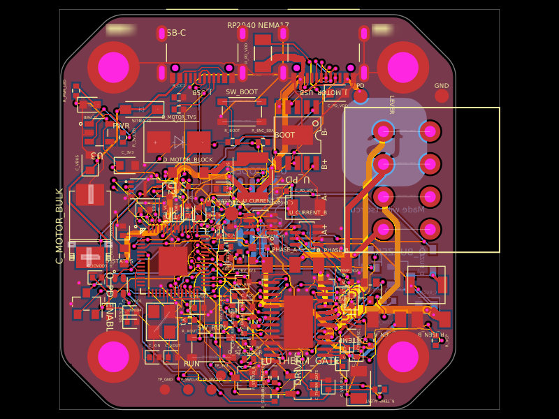 Similar packageastra/nema17-stepper-motor-controller-spring-clamp-rp2040A 4-layer RP2040 controller board that negotiates USB‑C PD motor power and drives a NEMA17 stepper via a DRV8825, with current sensing, thermal shutdown, RGB status LED, buzzer alarm, optional AS5600 encoder, protection/filtering, and test points.
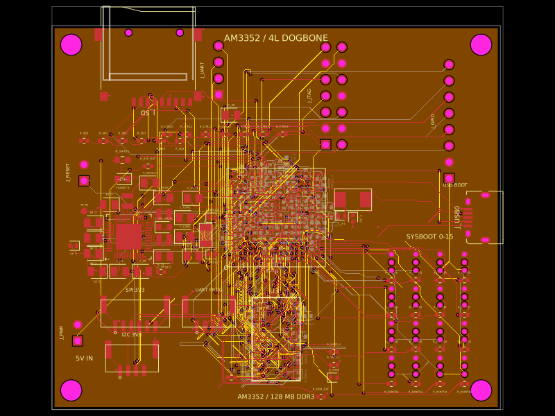 Discover something newseveibar/am3352-dev-board-4layer-dogboneDefines PCB footprints and pin mappings for a TI AM3352ZCZ100 processor, JST GH connectors, and assembly-part lookup helpers for capacitors, resistors, and headers.