imrishabh18/pedometer
This code defines and assembles a simple radio receiver hardware circuit using specific imported capacitors, inductors, RF connectors, and oscillator components with precise footprints and schematic attributes.
- Version
- 1.1.3
- License
- unset
- Stars
- 0
firmware/board.h
#ifndef STRIDE_BOARD_H
#define STRIDE_BOARD_H
#include <stdbool.h>
#include <stddef.h>
#include <stdint.h>
/* TI SysConfig DIO numbers (not QFN package pin numbers). I2C uses 7-bit addresses. */
enum { PIN_SCL=6, PIN_SDA=8, PIN_ACCEL_INT=12, PIN_GAUGE_INT=21,
 PIN_DISPLAY_ISOLATE=20, PIN_BUTTON_N=24, PIN_CHARGER_INT=13, PIN_PMIC_LP=11 };
enum { ADDR_BMA400=0x14, ADDR_BQ25150=0x6b, ADDR_BQ27427=0x55, ADDR_OLED=0x3c };
/* Implement these six hooks in the SimpleLink F3 application. Serialize I2C;
 * support repeated START + clock stretching, and enforce bounded timeouts. */
bool board_i2c_write(uint8_t address,const uint8_t *bytes,size_t length);
bool board_i2c_read_reg(uint8_t address,uint8_t reg,uint8_t *bytes,size_t length);
void board_gpio_write(unsigned dio,bool high);
void board_delay_us(uint32_t us);
uint64_t board_time_ms(void);
void board_wait_event_until(uint64_t deadline_ms);
#endif
Related Packages
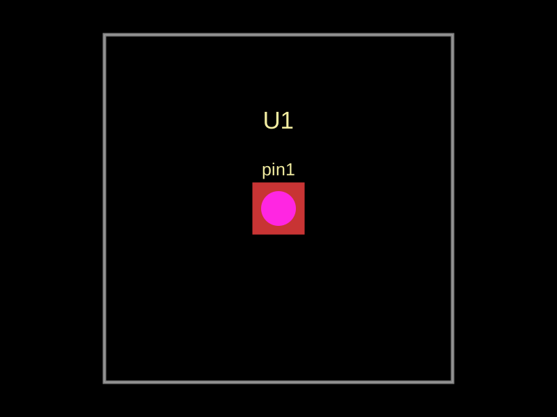 More from this authorimrishabh18/test-pcmThis code defines a 10mm by 10mm electronic circuit board containing a single pin-row chip with an associated 3D CAD model of the "MachineContactMedium" component.
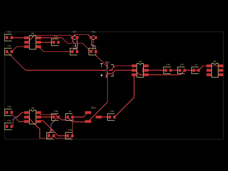 Similar packageMustafaMulla29/CC3235SF-tsxThis code defines a PCB layout with RF front-end components including RF switches (RTC6608OSP), band-pass filters, a diplexer, matching capacitors and inductors, and an antenna, all arranged to match a specific schematic for high-frequency radio signal routing.
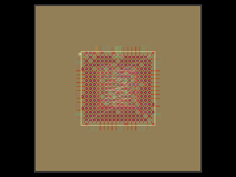 Discover something new0hmX/am3352This code defines a six-layer printed circuit board (PCB) design with a TI AM3352 microprocessor package, including precise pin mapping, power plane definition, fixed component placement, and PCB layout visualization.