imrishabh18/pedometer
This code defines and assembles a simple radio receiver hardware circuit using specific imported capacitors, inductors, RF connectors, and oscillator components with precise footprints and schematic attributes.
- Version
- 1.1.3
- License
- unset
- Stars
- 0
docs/no-via-in-pad.md
# BGA fanout and via-in-pad policy

**Via-in-pad is allowed, following the user's updated instruction.** The BQ25150 and BQ27427 remain fitted. A charger substitution is not needed to satisfy the current routing requirement.

`bga-fanout.ts` runs tscircuit's `FanoutSolver` on enclosed BGA balls with `allowViaInPad: true`. It validates seven local escapes across U2/U3, and passes their generated transitions to the capacity autorouter as terminal-via hints. The global router still connects every original net; the local fanout's plane termination does not declare electrical connectivity. Redundant same-net transitions can merge in the final board.

RF, crystal and SWCLK nets run in early `autoroutingphase` stages using Pipeline 9. The remaining board uses Pipeline 7 with through-via clearance handling. There are no explicit `<via />` elements, prescribed via coordinates or manual trace waypoints.

`bun run audit:bga-vias` inventories actual drill/land and drill/mask overlaps and **permits them**. See [current inventory](../review/bga-via-inventory.json). The optional `check:no-via-in-pad` command tests the superseded stricter policy; it is not part of the release checks.

Via-in-pad requires the [filled and copper-capped assembly process](assembly-requirements.md). Soldermask tenting alone is insufficient under these solder joints.

## Historical no-via-in-pad investigation

U2 has 0.40 mm pitch and 0.23 mm lands: its 0.17 mm channel cannot fit a 0.10 mm trace plus two 0.075 mm clearances. A larger board did not change that local geometry. Earlier no-via-in-pad experiments and replacement-part proposals in `review/no-via-in-pad-*.json` are historical evidence, not current fabrication requirements.
Related Packages
 More from this authorimrishabh18/test-pcmThis code defines a 10mm by 10mm electronic circuit board containing a single pin-row chip with an associated 3D CAD model of the "MachineContactMedium" component.
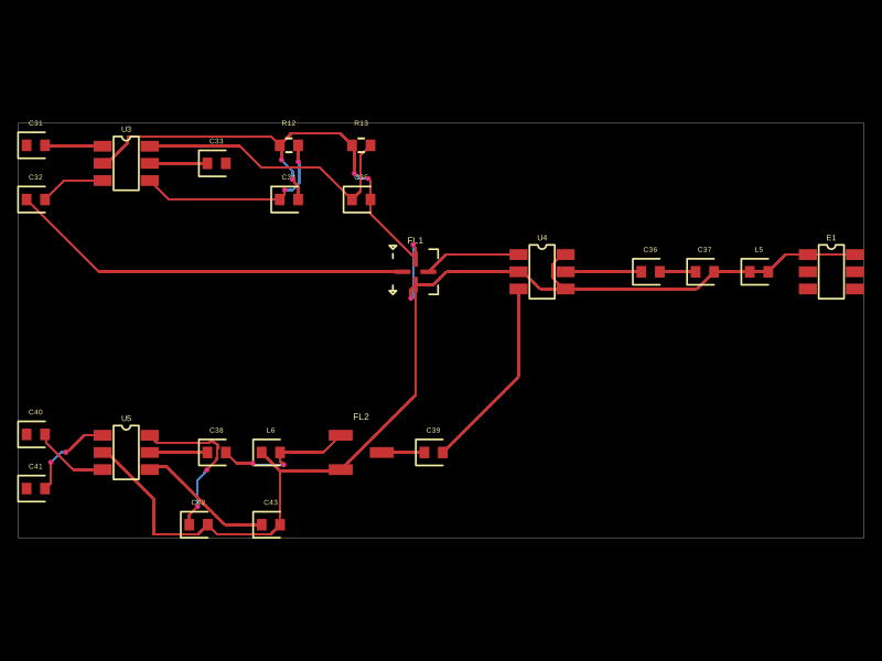 Similar packageMustafaMulla29/CC3235SF-tsxThis code defines a PCB layout with RF front-end components including RF switches (RTC6608OSP), band-pass filters, a diplexer, matching capacitors and inductors, and an antenna, all arranged to match a specific schematic for high-frequency radio signal routing.
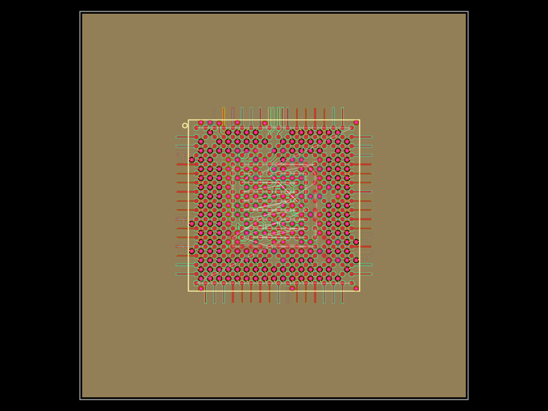 Discover something new0hmX/am3352This code defines a six-layer printed circuit board (PCB) design with a TI AM3352 microprocessor package, including precise pin mapping, power plane definition, fixed component placement, and PCB layout visualization.