imrishabh18/nema17-motor-controller-flex
An RP2040-based USB‑C/USB‑PD controller board that powers and drives a NEMA17 stepper via a DRV8825, with current/temperature/voltage monitoring, optional AS5600 encoder, buzzer/RGB status indicators, QSPI flash, and flexible motor/encoder connections.
- Version
- 1.2.0
- License
- unset
- Stars
- 0
index.circuit.tsx
PCB
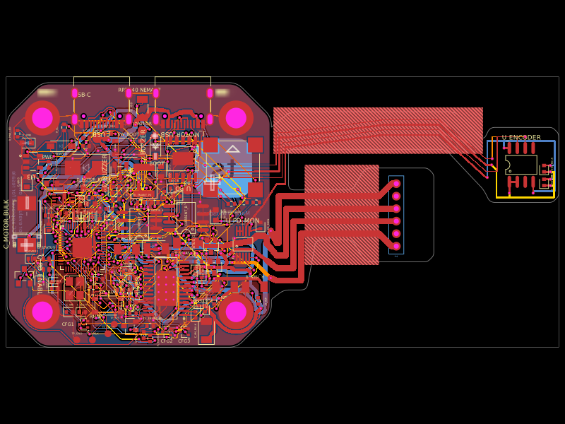
Schematic

import { Fragment } from "react";
import { Nema17Assembly, motorMountGap } from "./mechanical/Nema17Assembly";
import { motorStiffenerOutline } from "./mechanical/motor-stiffener";
import { autoLayoutSections } from "./schematic/AutoLayoutSections";
import { PdVoltageControlSection } from "./schematic/PdVoltageControlSection";
import { PdBusVoltageMonitorSection } from "./schematic/PdBusVoltageMonitorSection";
import jlcClearanceRules from "./pcb-rules.json";
import { ChipDescriptions } from "./schematic/ChipDescriptions";
import { tscircuitBottomLogo } from "./assets/tscircuit-logo-bottom";
import { Drv8825ThermalCopper } from "./schematic/Drv8825ThermalCopper";
import { OptionalEncoderSection } from "./schematic/OptionalEncoderSection";
import { CurrentTelemetrySection } from "./schematic/CurrentTelemetrySection";
import { StatusLedSection } from "./schematic/StatusLedSection";
import { ProductionTestPoints } from "./schematic/ProductionTestPoints";
import { FeedbackSection } from "./schematic/FeedbackSection";
import { flexBoardOutline, mainBoardOutline, encoderStiffenerOutline, motorConnectorStiffenerOutline, tailNecks, motorBendX, motorBendRadius, bendRadius, encoderBend } from "./mechanical/flex-layout";
import { savedRouting } from "./routing/saved-routing";
import { ControllerSections } from "./schematic/ControllerSections";
import {
	MotorDriverController,
	MotorDriverControlTraces,
	MotorDriverGroundTraces,
	MotorDriverPassives,
	MotorDriverPowerTraces,
	MotorDriverPrimaryGroundTraces,
	MotorDriverSenseAndControlTraces,
} from "./schematic/MotorDriverCoreSection";
import {
	MotorOutputConnectors,
	MotorOutputTraces,
} from "./schematic/MotorOutputsSection";
import {
	MotorPowerFilteringComponents,
	MotorPowerFilteringGroundTrace,
	MotorPowerFilteringSupplyTrace,
} from "./schematic/MotorPowerFilteringSection";
import {
	MotorPowerPdConnectorGroundTraces,
	MotorPowerPdControllers,
	MotorPowerPdInputTraces,
	MotorPowerPdPassives,
	MotorPowerPdPrimaryGroundTrace,
	MotorPowerPdProtocolTraces,
	MotorPowerPdSupportGroundTraces,
} from "./schematic/MotorPowerPdNegotiationSection";
import { SchematicSheets } from "./schematic/SchematicSheets";
import { ThermalProtectionComponents, ThermalProtectionTraces } from "./schematic/ThermalProtectionSection";

export default function Rp2040MotorController({
	routingDisabled = false,
  routingAlgorithm = savedRouting,
}: {
	routingDisabled?: boolean;
  routingAlgorithm?: typeof savedRouting;
} = {}) {
	// The DRV8825 footprint intentionally has thermal vias inside its exposed pad.
	// Core's placement check treats via-in-pad as a collision and skips routing.
	return autoLayoutSections(
    <board
      routingDisabled={routingDisabled}
      mountedTo="NEMA17.backface"
      mountOrientation="bottom_layer_toward_mount_face"
      mountGap={motorMountGap}
      mountRotation="NEMA17.wireside"
      mountRotationAnchor="rightedge"
			placementDrcChecksDisabled
			layers={4}
      // The saved full-board routes are intentional; opt into all remaining connections.
      routeRemaining
      material="flex"
      thickness="0.20mm"
			outline={flexBoardOutline}
			minViaHoleDiameter="0.3mm"
      minViaPadDiameter="0.5mm"
      minViaHoleEdgeToViaHoleEdgeClearance="0.2mm"
      minPlatedHoleDrillEdgeToDrillEdgeClearance="0.45mm"
      minViaEdgeToPadEdgeClearance="0.125mm"
      minTraceWidth={jlcClearanceRules.minimumMm.traceWidth}
      minTraceToPadEdgeClearance={jlcClearanceRules.minimumMm.padToTrace}
      // Native checks currently reuse this field for via-to-pad spacing.
      // checkJlcClearances separately enforces 0.15 mm between component pads.
      minPadEdgeToPadEdgeClearance={jlcClearanceRules.minimumMm.viaToPad}
      minBoardEdgeClearance={jlcClearanceRules.minimumMm.copperToBoardEdge}
			autorouterEffortLevel="2x"
			autorouterVersion="beta_pipeline7"
			autorouter={{
				local: true,
				algorithmFn: routingAlgorithm,
				groupMode: "subcircuit",
			}}
		>
			<net name="GND" />
			{/* Explicit net names keep labels consistent across the MCU subcircuit and sheets. */}
			<net name="DRIVER_STEP" connectsTo=".MCU > .U1 > .GPIO18" />
			<net name="DRIVER_DIR" connectsTo=".MCU > .U1 > .GPIO19" />
			<net name="DRIVER_RESET" connectsTo=".MCU > .U1 > .GPIO20" />
			<net name="MCU_ENABLE" connectsTo=".MCU > .U1 > .GPIO22" />
			<net name="TEMP_SDA" connectsTo=".MCU > .U1 > .GPIO26_ADC0" />
			<net name="TEMP_SCL" connectsTo=".MCU > .U1 > .GPIO27_ADC1" />
			<SchematicSheets />

			<group pcbX={-5.625} pcbY={-8.25}>
				<ControllerSections />
				<MotorDriverController />
				<MotorPowerPdControllers />
				<MotorOutputConnectors />
				<MotorPowerFilteringComponents />
				<MotorPowerPdPassives />
				<MotorDriverPassives />
				<ThermalProtectionComponents />

				<MotorDriverControlTraces />
				<MotorPowerPdInputTraces />
				<MotorPowerFilteringSupplyTrace />
				<MotorPowerPdProtocolTraces />
				<MotorDriverPowerTraces />
				<MotorDriverPrimaryGroundTraces />
				<MotorPowerPdPrimaryGroundTrace />
				<MotorPowerPdConnectorGroundTraces />
				<MotorPowerFilteringGroundTrace />
				<MotorPowerPdSupportGroundTraces />
				<MotorDriverGroundTraces />
				<MotorOutputTraces />
				<MotorDriverSenseAndControlTraces />
				<ThermalProtectionTraces />
			</group>

			<copperpour
				name="GND_TOP"
        outline={mainBoardOutline}
				layer="top"
				connectsTo="net.GND"
				clearance="0.21mm"
				padMargin="0.2mm"
				traceMargin="0.2mm"
				boardEdgeMargin="0.3mm"
				coveredWithSolderMask
			/>
			<copperpour
				name="GND_BOTTOM"
        outline={mainBoardOutline}
				layer="bottom"
				connectsTo="net.GND"
				clearance="0.21mm"
				padMargin="0.2mm"
				traceMargin="0.2mm"
				boardEdgeMargin="0.3mm"
				coveredWithSolderMask
			/>

			<group pcbX={0} pcbY={0} schX={0} schY={0}>
        {[-15.5,15.5].flatMap(x => [-15.5,15.5].map(y => (
          <group key={`${x}:${y}`} pcbX={0} pcbY={0} schX={0} schY={0}>
            <chip doNotPlace isSmt name={`MH${(x > 0 ? 2 : 0) + (y > 0 ? 1 : 0) + 1}`} pcbX={x} pcbY={y} schSheetName="motor_power" schX={x > 0 ? 11 : 8} schY={y > 0 ? -4 : -6}
              pinLabels={{pin1:["GND"]}} connections={{pin1:"net.GND"}}
              footprint={<footprint><platedhole portHints={["pin1"]} shape="circle" holeDiameter="3.3mm" outerDiameter="5.6mm" /></footprint>} />
          </group>
        )))}
        {/* Upper-left branding, viewed from underneath. Clear of vias without aperture cutouts. */}
        <silkscreengraphic imageUrl={tscircuitBottomLogo} width="9mm" height="9.340763mm"
          layer="bottom" pcbX={13.5} pcbY={7.5} />
        <silkscreentext text="Made with tscircuit" layer="bottom"
          pcbX={13.5} pcbY={0.3} fontSize="0.9mm" />
        {/* Vertical caution in the marked left-edge strip (board/top coordinates). */}
        <silkscreentext text="For evaluation only;" layer="bottom"
          pcbX={-18.95} pcbY={1} pcbRotation={270} fontSize="0.85mm" />
        <silkscreentext text="not FCC approved for resale" layer="bottom"
          pcbX={-20.05} pcbY={1} pcbRotation={270} fontSize="0.85mm" />
        {/* Large port labels stay visible beside the USB-C shells. */}
        <silkscreentext text="DATA" pcbX={-13.73} pcbY={19.35} fontSize="1.8mm" isKnockout knockoutPadding="0.18mm" />
        <silkscreentext text="PWR" pcbX={14.1} pcbY={19.35} fontSize="1.8mm" isKnockout knockoutPadding="0.18mm" />
        <silkscreentext text="RP2040 NEMA17" pcbX={0} pcbY={20} fontSize="0.8mm" />
      </group>
			{/* Explicit source joins also give the MCU sheet the same net labels. */}
			<trace name="LABEL_STEP" from=".MCU > .U1 > .GPIO18" to="net.DRIVER_STEP" schDisplayLabel="DRIVER_STEP" />
			<trace name="LABEL_DIR" from=".MCU > .U1 > .GPIO19" to="net.DRIVER_DIR" schDisplayLabel="DRIVER_DIR" />
			<trace name="LABEL_RESET" from=".MCU > .U1 > .GPIO20" to="net.DRIVER_RESET" schDisplayLabel="DRIVER_RESET" />
			<trace name="LABEL_ENABLE" from=".MCU > .U1 > .GPIO22" to="net.MCU_ENABLE" schDisplayLabel="MCU_ENABLE" />
			<trace name="LABEL_TEMP_SDA" from=".MCU > .U1 > .GPIO26_ADC0" to="net.TEMP_SDA" schDisplayLabel="TEMP_SDA" />
			<trace name="LABEL_TEMP_SCL" from=".MCU > .U1 > .GPIO27_ADC1" to="net.TEMP_SCL" schDisplayLabel="TEMP_SCL" />
      <FeedbackSection />
      <CurrentTelemetrySection />
      <StatusLedSection />
      <ProductionTestPoints />
      <OptionalEncoderSection />
      <Drv8825ThermalCopper />
      <ChipDescriptions />
      <PdVoltageControlSection />
      {/* Append new hardware after the validated layout so legacy route IDs remain stable. */}
      <PdBusVoltageMonitorSection />
      {tailNecks.map(neck => <Fragment key={neck.name}><keepout
        shape="rect" pcbX={(neck.x1+neck.x2)/2} pcbY={(neck.y1+neck.y2)/2}
        width={neck.x2-neck.x1} height={neck.y2-neck.y1} layers={["inner1","inner2","bottom"]} /></Fragment>)}
      <pcbbend name="ENCODER_RETURN_BEND" {...encoderBend} bendAngle={-180} bendRadius={bendRadius} bendSide="right" />
      <pcbbend name="MOTOR_TAIL_BEND" x1={motorBendX} y1={-4}
        x2={motorBendX} y2={4} bendAngle={-90} bendRadius={motorBendRadius} bendSide="right" />
      <pcbstiffener name="ENCODER_ISLAND_STIFFENER" shape="polygon" outline={encoderStiffenerOutline}
        layer="bottom" material="fr4" thickness="0.8mm" adhesiveThickness="0.05mm" />
      <pcbstiffener name="JST_ISLAND_STIFFENER" shape="polygon" outline={motorConnectorStiffenerOutline}
        layer="top" material="fr4" thickness="0.8mm" adhesiveThickness="0.05mm" />
      <pcbstiffener
        name="MOTOR_COMPONENTS_STIFFENER"
        shape="polygon"
        outline={motorStiffenerOutline}
        pcbX={0}
        pcbY={0}
        layer="bottom"
        material="fr4"
        thickness="0.8mm"
        adhesiveThickness="0.05mm"
      />
      <Nema17Assembly />
		</board>
	);
}
Related Packages
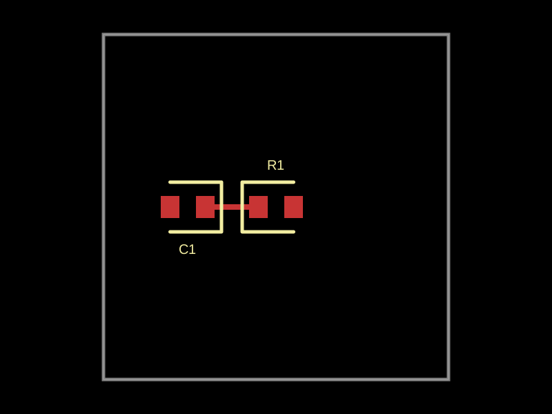 More from this authorimrishabh18/type-error-build-logThis code defines a 10mm by 10mm PCB layout with a 1kΩ resistor and a 1000pF capacitor connected by a trace, using 0402 surface-mount components.
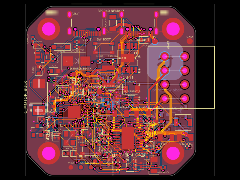 Similar packageastra/nema17-stepper-motor-controller-spring-clamp-rp2040A 4-layer RP2040 controller board that negotiates USB‑C PD motor power and drives a NEMA17 stepper via a DRV8825, with current sensing, thermal shutdown, RGB status LED, buzzer alarm, optional AS5600 encoder, protection/filtering, and test points.
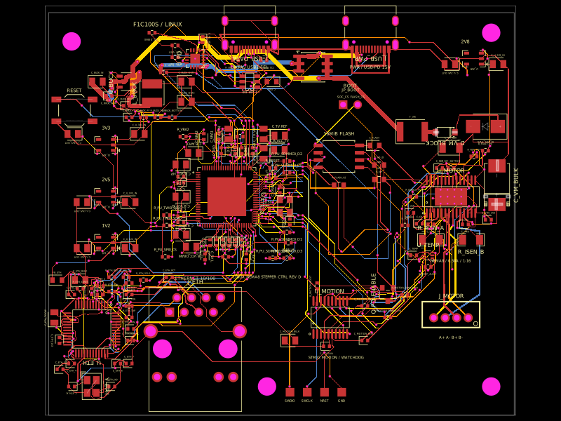 Discover something newshibosoftwaredev/f1c100s-linux-nema8-stepper-controllerRestores component part numbers and CAD models, removes test-point 3D bodies, and validates that solder paste exists only on top-side SMT pads without altering copper or DRC.