imrishabh18/nema17-motor-controller-flex
An RP2040-based USB‑C/USB‑PD controller board that powers and drives a NEMA17 stepper via a DRV8825, with current/temperature/voltage monitoring, optional AS5600 encoder, buzzer/RGB status indicators, QSPI flash, and flexible motor/encoder connections.
- Version
- 1.2.0
- License
- unset
- Stars
- 0
README.md
# NEMA17 motor controller — flex PCB

RP2040 / DRV8825 motor controller derived from `imrishabh18/rp2040-motor-controller` v1.0.43, with an encoder arm and a motor-connector arm.

- Controller and encoder components assemble on the flat top side. The six-contact motor socket is on the bottom side, as requested for the opposite face of its folded tip. The AS5600 and its bypass capacitors are populated.
- Encoder centre: 40 mm beyond the main board edge. Motor socket centre: 20 mm beyond the edge; six-position female PCB socket prototype.
- Four copper layers centrally, 0.20 mm flex substrate. Neck routing stays on top, with no vias, pads or stiffeners in the bends.
- Native `<pcbbend />` elements: 180° encoder return and −90° motor-socket bend alongside the rear-mounted motor, with 3.5 mm encoder and 5 mm motor neutral radii.
- Native FR-4 `<pcbstiffener />` backing: bottom under the main components and encoder; top on the motor-socket island, opposite its bottom-side socket. Each is 0.80 mm plus 0.05 mm adhesive. An open slot clears all six socket solder joints.
- Original 31 mm mounting-hole pitch remains unchanged.

```sh
bun install --frozen-lockfile
bun run build
bun run dev
```

`index.circuit.tsx` is the board entry point. `imports/` contains component footprints, `schematic/` defines the circuit sections, `routing/` preserves the saved copper, and `mechanical/` contains the outline, placements and stiffener polygon. `pcb-rules.json` supplies the board clearances. `vendor/` contains the required RP2040 subsystem and schematic layout helper, with their licenses.

The nominal folded encoder centre is `(0, 0, -7 mm)` relative to the main PCB neutral plane. Match the motor standoffs and shaft-magnet position to the sensor face and its required air gap before fabrication; XY alignment alone does not set the magnet gap. The bend radius assumes static installation, not continuous flexing.

## Wire-free motor adapter — prototype

J1 is a **female six-position PCB receptacle candidate**, Harwin **M22-7130642**, replacing the four-pin male JST header. The motor itself has male contacts, so another male header cannot mate to it. This custom flex-end adapter has no cable or flying leads. The socket assembles on the flat bottom side; the −90° motor-tail fold points its opening inward toward the motor. Its 270° PCB rotation preserves the contact numbering after the side change. The centred socket island is 15 mm tall and has native FR-4 backing with solder access.

The candidate socket uses 2 mm pitch, 0.80 mm drills, 0.5 mm square mating pins and is rated 2 A per contact. Its nominal body is 12.5 × 2.4 × 4.4 mm above the PCB. The 3D shape is an envelope proxy with six openings, not a supplier STEP model. See the [manufacturer drawing and specifications](https://www.harwin.com/products/M22-7130642).

**This is not a qualified JST-PH mating connector.** The exact header series, cavity clearance, usable pin length, retention, fold alignment and contact order on the [17HS15-1704S motor](https://au-stepperonline.com/nema-17-bipolar-42ncm-59-48oz-in-1-7a-42x42x37-5mm-4-wires-w-1m-cable-connector-17hs15-1704s.html) have not been verified. The body may interfere with the motor shroud. Check with an unpowered fit sample before ordering assembled boards; a different socket or custom contact carrier may be required. Support the stiffened island during insertion so the flex neck does not carry insertion force.

The following contact assignment is **provisional**, not a verified motor pinout. Contact 1 is at the low-Y end of J1 in the flat PCB top view; the socket has no polarizing key.

| Physical contact | Controller signal |
| --- | --- |
| 1 | A+ |
| 2 | Unconnected |
| 3 | A− |
| 4 | B+ |
| 5 | Unconnected |
| 6 | B− |

Confirm the two motor windings and unused positions with continuity measurements before powering. `motorContactMap` in `imports/MotorSocket6.tsx` configures the four channels; changing it requires regenerating and validating `routing/route-plan.json`. The saved-route guard deliberately refuses a stale layout. The two unused contacts are explicitly marked no-connect in the schematic.

The native exporter supports both bends. The live viewer fix is tracked in [3d-viewer PR #1062](https://github.com/tscircuit/3d-viewer/pull/1062).

## NEMA17 assembly reference

`mechanical/Nema17Assembly.tsx` adds the native `<assembly.motor />` NEMA17 model with a six-position PH-style male header. Its 42 × 42 × 37.5 mm body and 5 mm diameter, 22 mm front shaft follow the motor product specification. Cap details, connector shroud and header location use the generic modelprinter geometry, not a supplier CAD model.

The main PCB mounts to `NEMA17.backface`, with its underside toward the rear of the motor and the original 31 mm hole pattern centred on the motor axis. `motorMountGap ≈ 9.196 mm` is computed for nominal header/socket alignment, not a measured or validated mounting stack. The encoder fold remains at `(0, 0, −7 mm)`; no rear shaft or magnet is invented in the motor model. Socket engagement, header location, mounting screws, magnet installation and sensor air gap still need measurement on the actual motor. The motor socket is centred at Y = 0. Its folded opening plane and all six contact axes coincide with the generic model header mouth at X = 27 mm, Z ≈ −11.796 mm, with opposing entry directions. This establishes nominal alignment for insertion; shroud clearance and actual contact engagement still require a fit prototype.

The encoder arm rises above the centred motor island in the flat outline so the two tongues stay separate. Its diagonal 180° bend still returns the sensor to the motor axis. The 20 mm motor reach and 40 mm encoder reach (board edge to component centre in flat X) remain unchanged. All routes crossing a bend are straight, perpendicular to its axis, and confined to the top copper layer.
Related Packages
 More from this authorimrishabh18/type-error-build-logThis code defines a 10mm by 10mm PCB layout with a 1kΩ resistor and a 1000pF capacitor connected by a trace, using 0402 surface-mount components.
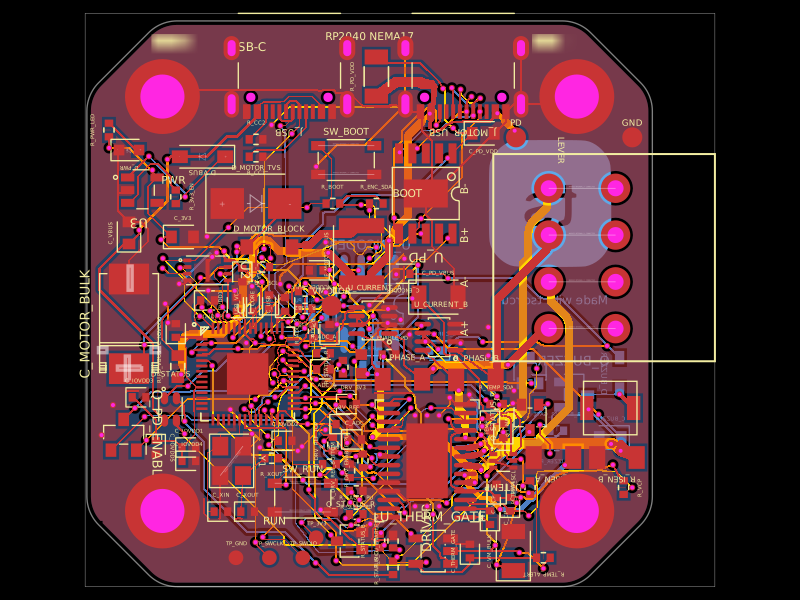 Similar packageastra/nema17-stepper-motor-controller-spring-clamp-rp2040A 4-layer RP2040 controller board that negotiates USB‑C PD motor power and drives a NEMA17 stepper via a DRV8825, with current sensing, thermal shutdown, RGB status LED, buzzer alarm, optional AS5600 encoder, protection/filtering, and test points.
 Discover something newshibosoftwaredev/f1c100s-linux-nema8-stepper-controllerRestores component part numbers and CAD models, removes test-point 3D bodies, and validates that solder paste exists only on top-side SMT pads without altering copper or DRC.