imrishabh18/fitness_watch
This circuit integrates an ESP-12E microcontroller with various sensors, relays, and power management components, including an AO3400A transistor for switching loads, to enable wireless control and sensing functions.
- Version
- 1.0.11
- License
- unset
- Stars
- 0
VALIDATION.md
# External-battery watch — 1.0.11-external-battery

USB-C and onboard charging have been removed. Use an externally charged, protected 1S LiPo through J1; pin 1 is positive and pin 2 is ground. J1 feeds the AP2112K input and enable directly, with C3 retained as input bypass. The 3.3 V and 1.8 V regulated rails remain separate from VBAT. J2 remains the 3.3 V UART programming header.

Removed: J3 USB-C, U3 TP4056, R1/R2/D1 charge programming/indicator, C1/C2 charge-input/battery bypass, R10/R11 USB-C CC resistors, and Q2/D3/R12 USB/battery power-selection circuit. The remaining regulator bypass capacitors are retained.

M1 is on the top at (18, 10.5) mm, in the former USB/charger area, clear of J1. Its driver Q1 is at (17, 6), flyback diode D2 at (13, 6), gate resistor R9 at (13, 3), and gate pulldown R13 at (17, 3). Motor polarity and diode orientation are preserved. The MAX30102 remains wrist-facing on the bottom.

## Validation

- Global tscircuit CLI 0.0.2506, matching the pinned project dependency.
- PCB DRC: 0 error objects.
- tsci check: 0 errors, 33 schematic/component annotation warnings.
- Netlist: 0 errors, 0 warnings.
- Gerber-based short check: no shorts.
- TypeScript: passed.
- Connectivity assertions: 69 passed, including the new J1-to-regulator path.
- Board BOM: 36 placements, 22 exact JLC part numbers, all sufficient for one watch in the refreshed stock snapshot.

The routing was regenerated. Sensor ground routes were repaired around the retained MEMS keepout; a sensor supply segment uses 0.15 mm copper for fanout, and the board-edge ground link retains 0.8 mm copper. Saved routes include net and pad-position guards; no design checks were disabled.

## Assembly scope

No charging function remains on this board. Unplug the cell and use an external charger matched to that battery. A protected battery, enclosure and optical window are still external assemblies. The wired motor's vendor 3D model is upright; final adhesive mounting and case height require mechanical validation. The AP2112K is a linear regulator and its output falls below 3.3 V as the battery approaches dropout. Firmware adaptation and power/thermal testing remain outstanding; DRC clearance is not a completed functional prototype test.
Related Packages
 More from this authorimrishabh18/boost-converterThis code defines a PCB schematic and 3D model layout focusing on a power conversion circuit with components like USB-C connector, MT3608 step-up regulator, inductor, diode, input/output capacitors, and resistors arranged on a double-layer PCB.
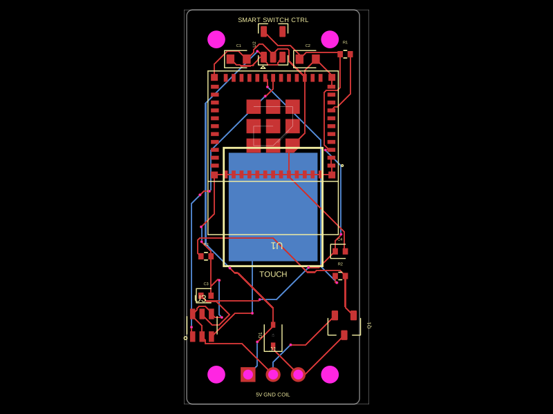 Similar packagehrithik18k/smart-switch-pcbThe AO3400A component models a SOT-23 N-channel MOSFET with labeled pins for Gate, Source, and Drain, including 3D CAD models and schematic symbols for electronic circuit design.
 Discover something newShiboSoftwareDev/mspm0g3507-usb-c-dev-boardThe circuit assembles a USB-C port with integrated ESD protection, power regulation, UART interface, and microcontroller (MSPM0G3507) with supporting components for USB data lines, CC termination, I2C, SPI, reset circuitry, and indicator LEDs.