gokul/mpu6050-mini
Compact 3.3 V MPU-6050 IMU breakout on an 11×12 mm PCB, with decoupling capacitors, I²C pull-ups, AD0 address pulldown, ground plane, and a 6-pin host header.
- Version
- 1.0.1
- License
- unset
- Stars
- 0
README.md
PCB
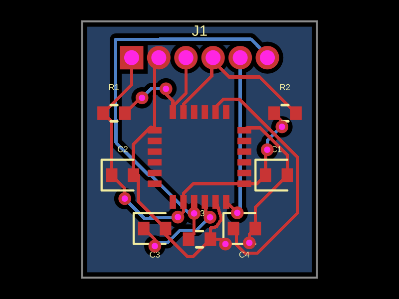
# MPU-6050 Mini

An 11 x 12 mm, two-layer MPU-6050 I2C breakout for a **3.3 V supply and 3.3 V logic**. The board has a six-hole, 1.27 mm-pitch connector footprint and ships without a fitted header. Pin 1 is the square pad at the left when viewed from the component side with the connector at the top.

| J1 pin | Signal | Function |
| --- | --- | --- |
| 1 | 3V3 | Regulated 3.3 V input |
| 2 | GND | Ground |
| 3 | SDA | I2C data |
| 4 | SCL | I2C clock |
| 5 | INT | MPU-6050 interrupt output |
| 6 | AD0 | Address select input |

R3 pulls AD0 low, giving I2C address `0x68`. Drive AD0 to 3.3 V for `0x69`. R1 and R2 are 4.7 kOhm I2C pullups to 3.3 V. C1-C4 implement the four local capacitors in the [TDK MPU-6000/MPU-6050 reference circuit](https://product.tdk.com/system/files/dam/doc/product/sensor/mortion-inertial/imu/data_sheet/mpu-6000-datasheet1.pdf). CLKIN and FSYNC are grounded; auxiliary I2C and reserved pins are unused.

The MPU-6050 exposed center die pad is intentionally **not soldered**. The footprint has perimeter pads only, following the manufacturer's stress guidance. Do not add a center paste aperture when making the assembly stencil.

## Manufacturing

- Fabrication archive: `mpu6050-mini-fab.zip` (top/bottom copper, solder mask and silkscreen, board outline, and Excellon drill).
- Board: 11 x 12 mm, 2-layer FR-4, 1.6 mm thickness.
- Minimum routed trace width: 0.15 mm. Vias: 0.30 mm drill, 0.60 mm pad.
- QFN-24 perimeter pad pitch: 0.50 mm. Assembly requires a controlled stencil and reflow process. J1 is hand-soldered if a header is needed.
- `mpu6050-mini-kicad.zip` is an editable KiCad schematic/PCB export. It is not required by the fab house.
- `mpu6050-mini-schematic.pdf` is the schematic reference.

The BOM is in `bom.csv`. Confirm MPU-6050 stock and footprint against the exact purchased package before ordering assembly. The generated tscircuit board was typechecked and checked with zero circuit errors; physical hardware has not been built or electrically tested.

## Rebuild

Install dependencies with `npm install`, then run `npx tsci build index.circuit.tsx --disable-parts-engine` or `npx tsci dev`. The source file is `index.circuit.tsx`.
Related Packages
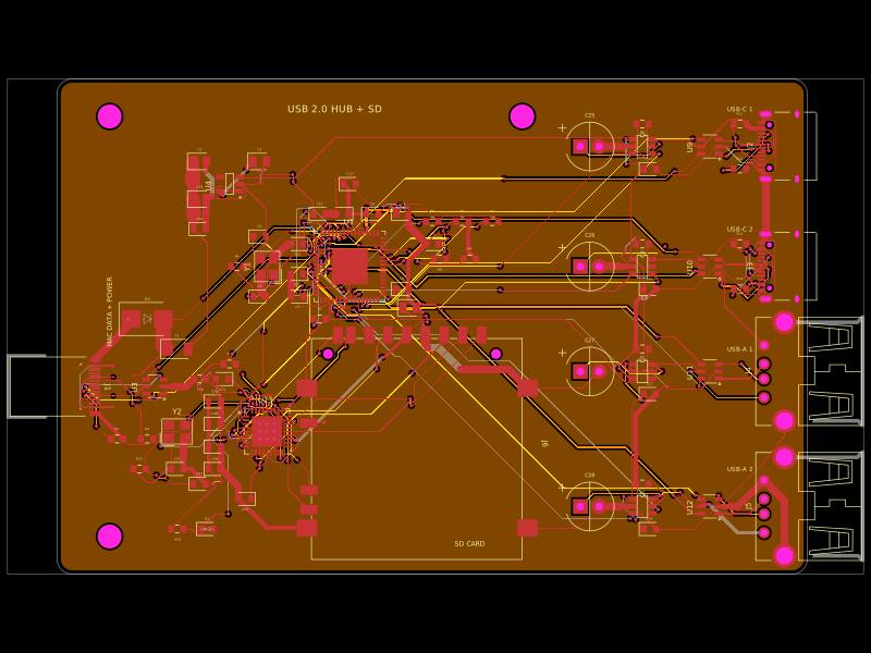 More from this authorgokul/usb-hub-boardA 4-layer 100×66 mm USB 2.0 hub board with a USB‑C upstream port, four protected downstream USB‑C/USB‑A ports, an integrated SD card reader, USB hub controllers, 3.3 V regulation, ESD protection, current-limited power switches, crystal oscillators, and filtering/passive components.
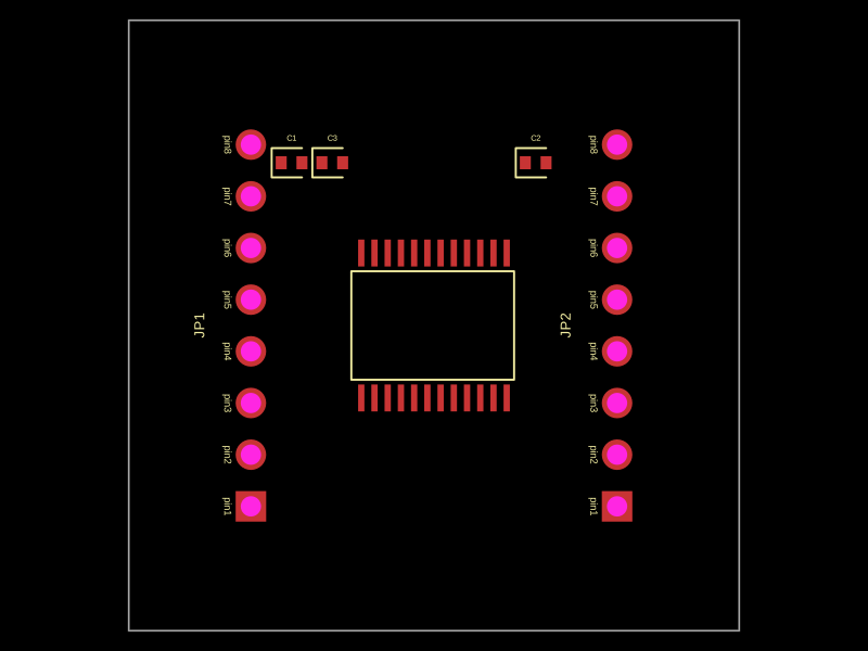 Similar packageimrishabh18/motor-driver-breakout"A 30x30mm TB6612FNG motor driver board with dual 8-pin headers and bypass capacitors for motor control and power regulation"
This summary captures the key physical characteristics:
- Uses TB6612FNG motor driver chip
- 30x30mm board size
- Dual 8-pin headers (JP1 and JP2)
- Includes decoupling capacitors (C1, C2, C3)
- Purpose is motor control and power management
Similar packageimrishabh18/motor-driver-breakout"A 30x30mm TB6612FNG motor driver board with dual 8-pin headers and bypass capacitors for motor control and power regulation"
This summary captures the key physical characteristics:
- Uses TB6612FNG motor driver chip
- 30x30mm board size
- Dual 8-pin headers (JP1 and JP2)
- Includes decoupling capacitors (C1, C2, C3)
- Purpose is motor control and power management Discover something newShiboSoftwareDev/nema8-20mm-pd-mini-controllerA 20 mm four-layer USB‑C PD 9 V NEMA8 stepper-driver board using CH224K power negotiation/protection and a TMC2209 with current sensing, motor connector, and STEP/DIR/UART control test points.