gokul/lora-device
A compact LoRa/GNSS device PCB integrating an SX1262 radio, GNSS module, USB/UART interface, 1.5 µH inductor, LiPo battery connector with NTC, and supporting passives.
- Version
- 0.1.6
- License
- unset
- Stars
- 0
sections/PowerSection.tsx
import { BQ24074RGTR } from "../imports/BQ24074RGTR";
import { TPS63021DSJR } from "../imports/TPS63021DSJR";
import { USBLC6_2SC6 } from "../imports/USBLC6_2SC6";
import { TYPE_C_31_M_12 } from "../imports/TYPE_C_31_M_12";
import { BatteryConnector } from "../components/BatteryConnector";
import { InductorFootprint } from "../components/InductorFootprint";
import { LTST_C190KGKT } from "../imports/LTST_C190KGKT";
import { LTST_C190KFKT } from "../imports/LTST_C190KFKT";
import { R, C } from "../components/passives";

export function PowerSection() {
  return (
    <>
      <TYPE_C_31_M_12
        schSectionName="Usb"
        name="J1"
        allowOffBoard
        pcbX={18}
        pcbY={-35}
        pcbRotation={0}
        connections={{
          VBUS1: "net.VBUS",
          VBUS2: "net.VBUS",
          GND1: "net.GND",
          GND2: "net.GND",
          EH1: "net.GND",
          EH2: "net.GND",
          EH3: "net.GND",
          EH4: "net.GND",
          CC1: "net.CC1",
          CC2: "net.CC2",
          DP1: "net.USB_DP",
          DP2: "net.USB_DP",
          DN1: "net.USB_DM",
          DN2: "net.USB_DM",
        }}
        noConnect={["SBU1", "SBU2"]}
      />
      <R
        schSectionName="Usb"
        name="R1"
        pcbRotation={180}
        resistance="5.1k"
        pcbX={10.5}
        pcbY={-30}
        connections={{ pin1: "net.CC1", pin2: "net.GND" }}
      />
      <R
        schSectionName="Usb"
        name="R2"
        pcbRotation={180}
        resistance="5.1k"
        pcbX={10.5}
        pcbY={-28.4}
        connections={{ pin1: "net.CC2", pin2: "net.GND" }}
      />

      <USBLC6_2SC6
        schSectionName="Usb"
        name="U6"
        displayName="U6 USB ESD / 5 V"
        pcbX={18}
        pcbY={-28.5}
        internallyConnectedPins={[
          ["pin1", "pin6"],
          ["pin3", "pin4"],
        ]}
        connections={{
          pin1: "net.USB_DP",
          pin6: "net.USB_DP",
          pin3: "net.USB_DM",
          pin4: "net.USB_DM",
          pin2: "net.GND",
          pin5: "net.VBUS",
        }}
      />

      <C
        schSectionName="Usb"
        name="C1"
        capacitance="100nF"
        pcbX={22}
        pcbY={-28.5}
        connections={{ pin1: "net.VBUS", pin2: "net.GND" }}
      />
      <C
        schSectionName="Usb"
        name="C2"
        pcbRotation={90}
        capacitance="1uF"
        pcbX={20.75}
        pcbY={-17}
        connections={{ pin1: "net.VBUS", pin2: "net.GND" }}
      />

      <BQ24074RGTR
        schSectionName="Charger"
        name="U2"
        pcbRotation={0}
        displayName="U2 Charger / 250 mA"
        pcbX={20}
        pcbY={-21}
        noConnect={["TMR", "ITERM"]}
        internallyConnectedPins={[
          ["BAT1", "BAT2"],
          ["OUT1", "OUT2"],
          ["VSS", "EP"],
        ]}
        connections={{
          TS: "net.BAT_TEMP",
          BAT1: "net.VBAT",
          BAT2: "net.VBAT",
          N_CE: "net.GND",
          EN2: "net.GND",
          EN1: "net.USB_500MA",
          N_PGOOD: "net.USB_PGOOD",
          VSS: "net.GND",
          N_CHG: "net.CHARGE_LED",
          OUT1: "net.VSYS",
          OUT2: "net.VSYS",
          ILIM: "net.CHARGER_ILIM",
          IN: "net.VBUS",
          ISET: "net.CHARGER_ISET",
          EP: "net.GND",
        }}
      />
      <R
        schSectionName="Charger"
        name="R3"
        pcbRotation={0}
        resistance="3.57k"
        pcbX={16}
        pcbY={-16.5}
        connections={{ pin1: "net.CHARGER_ISET", pin2: "net.GND" }}
      />
      <R
        schSectionName="Charger"
        name="R4"
        pcbRotation={0}
        resistance="3.24k"
        pcbX={23}
        pcbY={-17}
        connections={{ pin1: "net.CHARGER_ILIM", pin2: "net.GND" }}
      />
      <R
        schSectionName="Charger"
        name="R5"
        resistance="10k"
        pcbX={14}
        pcbY={-27}
        connections={{ pin1: "net.V3_3", pin2: "net.USB_500MA" }}
      />
      <R
        schSectionName="Charger"
        name="R6"
        resistance="10k"
        pcbX={12}
        pcbY={-16.5}
        connections={{ pin1: "net.V3_3", pin2: "net.USB_PGOOD" }}
      />
      <C
        schSectionName="Charger"
        name="C3"
        pcbRotation={180}
        capacitance="10uF"
        footprint="0805"
        pcbX={16}
        pcbY={-21}
        connections={{ pin1: "net.VBAT", pin2: "net.GND" }}
      />
      <C
        schSectionName="Charger"
        name="C4"
        schMarginX={0.6}
        schMarginY={0.6}
        capacitance="10uF"
        footprint="0805"
        pcbX={23.2}
        pcbY={-24}
        pcbRotation={270}
        connections={{ pin1: "net.VSYS", pin2: "net.GND" }}
      />
      <BatteryConnector
        schSectionName="Charger"
        name="J2"
        manufacturerPartNumber="B3B-PH-K-S(LF)(SN)"
        supplierPartNumbers={{ jlcpcb: ["C131339"] }}
        pcbX={-21}
        pcbY={-7.5}
        connections={{
          pin1: "net.VBAT",
          pin2: "net.GND",
          pin3: "net.BAT_TEMP",
        }}
      />

      <TPS63021DSJR
        schSectionName="Regulator"
        name="U3"
        pcbRotation={0}
        displayName="U3 Buck-boost / 3.3 V"
        pcbX={6}
        pcbY={-21}
        internallyConnectedPins={[
          ["VIN1", "VIN2"],
          ["VOUT1", "VOUT2"],
          ["L11", "L12"],
          ["L21", "L22"],
          ["GND", "PGND"],
        ]}
        noConnect={["PG"]}
        connections={{
          VINA: "net.VSYS",
          GND: "net.GND",
          FB: "net.V3_3",
          VOUT1: "net.V3_3",
          VOUT2: "net.V3_3",
          L21: "net.SW_L2",
          L22: "net.SW_L2",
          L11: "net.SW_L1",
          L12: "net.SW_L1",
          VIN1: "net.VSYS",
          VIN2: "net.VSYS",
          EN: "net.VSYS",
          PS: "net.GND",
          PGND: "net.GND",
        }}
      />
      <InductorFootprint
        schSectionName="Regulator"
        name="L1"
        pcbRotation={270}
        manufacturerPartNumber="XFL4020-152MEC"
        pcbX={11.1}
        pcbY={-21}
        connections={{ pin1: "net.SW_L1", pin2: "net.SW_L2" }}
      />

      <C
        schSectionName="Regulator"
        name="C5"
        capacitance="10uF"
        footprint="0805"
        pcbX={5}
        pcbY={-16.5}
        pcbRotation={90}
        connections={{ pin1: "net.VSYS", pin2: "net.GND" }}
      />
      <C
        schSectionName="Regulator"
        name="C6"
        capacitance="10uF"
        footprint="0805"
        pcbX={8}
        pcbY={-16.5}
        pcbRotation={90}
        connections={{ pin1: "net.VSYS", pin2: "net.GND" }}
      />
      <C
        schSectionName="Regulator"
        name="C7"
        pcbRotation={180}
        capacitance="100nF"
        pcbX={1.9}
        pcbY={-22.5}
        connections={{ pin1: "net.VSYS", pin2: "net.GND" }}
      />

      <C
        schSectionName="Regulator"
        name="C8"
        capacitance="22uF"
        footprint="0805"
        pcbX={4}
        pcbY={-25.7}
        pcbRotation={270}
        connections={{ pin1: "net.V3_3", pin2: "net.GND" }}
      />
      <C
        schSectionName="Regulator"
        name="C9"
        capacitance="22uF"
        footprint="0805"
        pcbX={7}
        pcbY={-25.7}
        pcbRotation={270}
        connections={{ pin1: "net.V3_3", pin2: "net.GND" }}
      />
      <C
        schSectionName="Regulator"
        name="C10"
        capacitance="22uF"
        footprint="0805"
        pcbX={10}
        pcbY={-25.7}
        pcbRotation={270}
        connections={{ pin1: "net.V3_3", pin2: "net.GND" }}
      />

      <R
        schSectionName="PowerIndicators"
        name="R7"
        resistance="2.2k"
        pcbX={11}
        pcbY={-2.5}
        connections={{ pin1: "net.V3_3", pin2: "net.POWER_LED" }}
      />
      <R
        schSectionName="PowerIndicators"
        name="R8"
        resistance="2.2k"
        pcbRotation={180}
        pcbX={15}
        pcbY={-2.5}
        connections={{ pin1: "net.VBUS", pin2: "net.CHARGE_LED_A" }}
      />
      <LTST_C190KGKT
        schSectionName="PowerIndicators"
        name="D1"
        schOrientation="pos_top"
        color="green"
        pcbX={11}
        pcbY={-5.5}
        connections={{ anode: "net.POWER_LED", cathode: "net.GND" }}
      />
      <LTST_C190KFKT
        schSectionName="PowerIndicators"
        name="D2"
        schOrientation="pos_top"
        color="orange"
        pcbX={15}
        pcbY={-5.5}
        connections={{ anode: "net.CHARGE_LED_A", cathode: "net.CHARGE_LED" }}
      />
      <trace
        name="SwitchL1Bridge"
        from=".U3 > .L12"
        to=".U3 > .L11"
        thickness={0.3}
        pcbPath={[".U3 > .L12", ".U3 > .L11"]}
      />
      <trace
        name="SwitchL2Bridge"
        from=".U3 > .L22"
        to=".U3 > .L21"
        thickness={0.3}
        pcbPath={[".U3 > .L22", ".U3 > .L21"]}
      />
      <trace
        name="SwitchL1Path"
        from=".U3 > .L11"
        to=".L1 > .pin1"
        thickness={0.4}
        pcbPath={[
          ".U3 > .L11",
          { x: 2.5, y: 1.450086 },
          { x: 2.765086, y: 1.185 },
          ".L1 > .pin1",
        ]}
      />
      <trace
        name="SwitchL2Path"
        from=".U3 > .L21"
        to=".L1 > .pin2"
        thickness={0.4}
        pcbPath={[
          ".U3 > .L21",
          { x: 2.5, y: -1.450086 },
          { x: 2.765086, y: -1.185 },
          ".L1 > .pin2",
        ]}
      />
    </>
  );
}
Related Packages
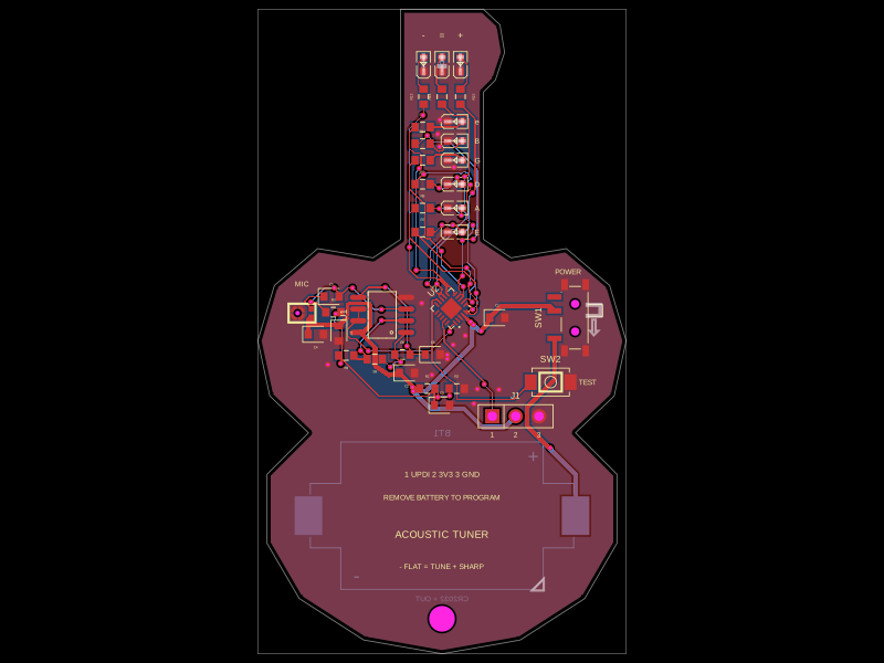 More from this authorgokul/acoustic-guitar-tunerThis code defines the physical pin configuration and footprint layouts for the ATtiny1616 microcontroller and a matching tactile switch component, including their key hardware connection points, dimensions, and 3D models.
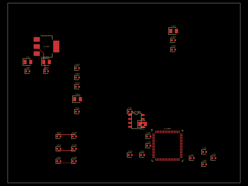 Similar packagecodezonly/pt1This design implements a compact embedded hardware module combining a Seeed XIAO ESP32-C6 microcontroller, a RushFPV GNSS Mini M10 GPS module, and an SX1262 LoRa transceiver, integrated with USB-C power/data, user interface LEDs and buttons, decoupling capacitors, and antenna connectors for GPS and LoRa communication.
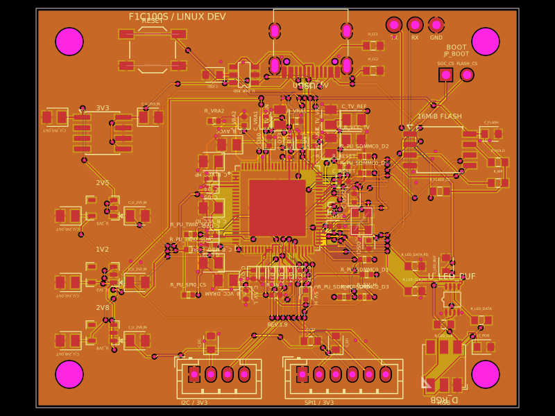 Discover something newseveibar/f1c100s-linux-dev-boardA 4-layer F1C100S Linux development carrier board with USB‑C power/data, multi-rail LDOs, SPI NOR flash, reset/boot interfaces, I²C/SPI/UART headers, ESD protection, and a buffered 5‑V clocked RGB LED.