gokul/lora-device
A compact LoRa/GNSS device PCB integrating an SX1262 radio, GNSS module, USB/UART interface, 1.5 µH inductor, LiPo battery connector with NTC, and supporting passives.
- Version
- 0.1.6
- License
- unset
- Stars
- 0
docs/references.md
# Design references

The idea follows the battery-powered LoRa + GNSS tracker architecture illustrated by the [LILYGO LoRa/T-Beam boards](https://github.com/Xinyuan-LilyGO/LilyGo-LoRa-Series). This board is a separate design, not a pin-compatible T-Beam clone.

Primary component references used for pin assignments and layout:

- [u-blox SAM-M10Q integration manual](https://content.u-blox.com/sites/default/files/documents/SAM-M10Q_IntegrationManual_UBX-22020019.pdf): ground plane, antenna clearance, supply and UART integration.
- [u-blox SAM-M10Q datasheet](https://content.u-blox.com/sites/default/files/documents/SAM-M10Q_DataSheet_UBX-22013293.pdf).
- [Seeed Wio-SX1262 module datasheet](https://files.seeedstudio.com/products/SenseCAP/Wio_SX1262/Wio-SX1262_Module_Datasheet.pdf) and [module integration page](https://wiki.seeedstudio.com/wio_sx1262/).
- [ESP32-S3-WROOM-1 datasheet](https://www.espressif.com/sites/default/files/documentation/esp32-s3-wroom-1_wroom-1u_datasheet_en.pdf).
- [TI BQ24074 datasheet](https://www.ti.com/lit/ds/symlink/bq24074.pdf): charger, input-mode truth table, thermistor, current setting and power path.
- [TI TPS63021 datasheet](https://www.ti.com/lit/ds/symlink/tps63021.pdf): buck-boost components and layout.
- [TI TPS22918 datasheet](https://www.ti.com/lit/ds/symlink/tps22918.pdf).
- [TI SN74LVC2G125 datasheet](https://www.ti.com/lit/ds/symlink/sn74lvc2g125.pdf): powered-off I/O isolation.
- [Coilcraft XFL4020 datasheet](https://www.coilcraft.com/getmedia/50632d43-da1b-4cdb-8ab4-3029cab51df3/xfl4020.pdf).
- [tscircuit handbook](https://github.com/tscircuit/handbook/tree/main).

The GNSS antenna sets much of the board area: the manufacturer characterizes it using a 50 × 50 mm ground plane and recommends separation from surrounding parts. The largely empty upper board area is intentional antenna clearance. The board is four layers to provide a ground reference beneath the routing and the antenna.
Related Packages
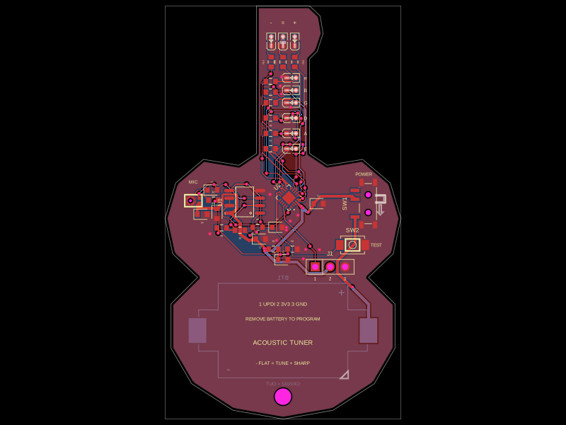 More from this authorgokul/acoustic-guitar-tunerThis code defines the physical pin configuration and footprint layouts for the ATtiny1616 microcontroller and a matching tactile switch component, including their key hardware connection points, dimensions, and 3D models.
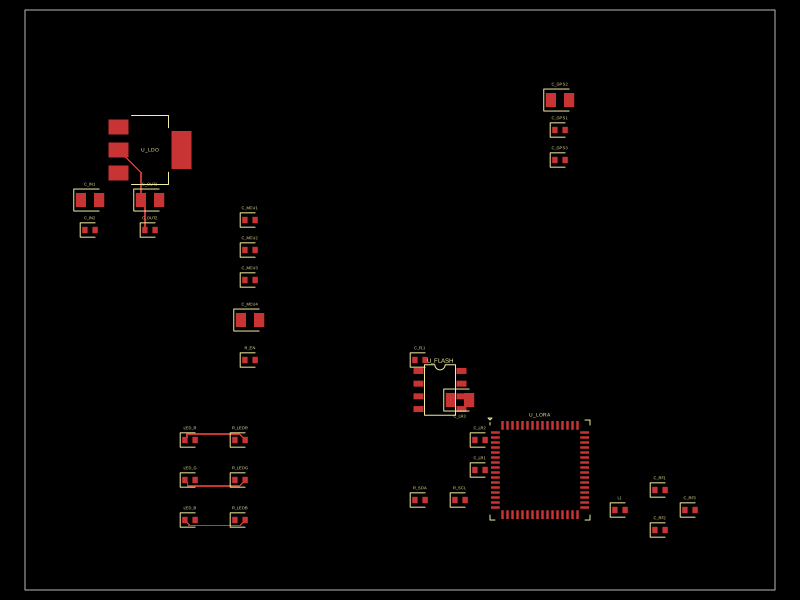 Similar packagecodezonly/pt1This design implements a compact embedded hardware module combining a Seeed XIAO ESP32-C6 microcontroller, a RushFPV GNSS Mini M10 GPS module, and an SX1262 LoRa transceiver, integrated with USB-C power/data, user interface LEDs and buttons, decoupling capacitors, and antenna connectors for GPS and LoRa communication.
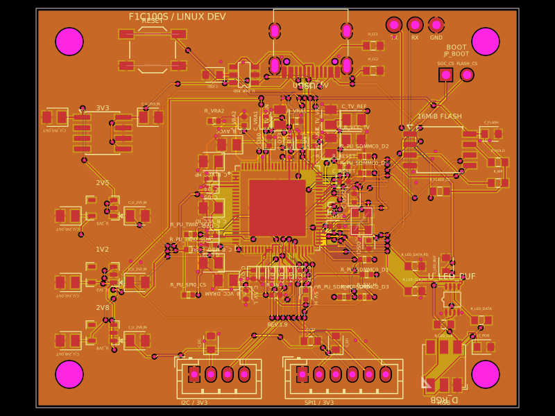 Discover something newseveibar/f1c100s-linux-dev-boardA 4-layer F1C100S Linux development carrier board with USB‑C power/data, multi-rail LDOs, SPI NOR flash, reset/boot interfaces, I²C/SPI/UART headers, ESD protection, and a buffered 5‑V clocked RGB LED.