gokul/flex-led-wristband
A flexible, rechargeable touch wristband PCB with MCP73831 Li-ion charging, switched 3.0 V regulation, ATtiny402 control, TTP223 capacitive touch sensing, and six charlieplexed red LEDs plus power/charge indicators.
- Version
- 0.0.3
- License
- unset
- Stars
- 0
FOOTPRINT_REVIEW.txt
FOOTPRINT AND ELECTRICAL REVIEW — REV 0.0.3

All dimensions in mm, top view. Source pin numbers checked against manufacturer-authored drawings; generic package names alone were not treated as verification.

U1 ATtiny402-SSN: SOIC-8 recommended pads 1.55 x 0.60, row-centre spacing 5.40, pitch 1.27. Microchip DS40002318A, p499 land pattern; pin diagram p14. 1=VDD, 2=PA6, 3=PA7, 4=PA1, 5=PA2, 6=PA0/UPDI, 7=PA3, 8=GND. At 3 V select a permitted CPU frequency (5 MHz recommended); preserve UPDI fuse. PA3 intentionally unused.
https://ww1.microchip.com/downloads/aemDocuments/documents/MCU08/ProductDocuments/DataSheets/ATtiny202-204-402-404-406-DataSheet-DS40002318.pdf

U2 MCP73831T-2ACI/OT: Microchip DS20001984H, recommended SOT-23-5 pads 1.10 x 0.60, row-centre spacing 2.80, pitch 0.95. 1=STAT, 2=VSS, 3=VBAT, 4=VDD, 5=PROG. 20 kohm sets nominal 50 mA charge; option -2 is 4.2 V. 4.7 uF on input/battery. At 5 V input and 3 V battery, worst normal constant-current dissipation is approximately 0.10 W. No load sharing: switch must be OFF for valid charger termination. STAT LED sourced from 5 V through 3.3 kohm. Grouped coverlay openings per pin row; solder paste stays individual pads.
https://ww1.microchip.com/downloads/aemDocuments/documents/APID/ProductDocuments/DataSheets/MCP73831-Family-Data-Sheet-DS20001984H.pdf

U4 MCP1700T-3002E/TT: Microchip DS20001826F p19 land pattern, pads 1.05 x 0.65, row-centre spacing 2.30, pitch 0.95. 1=GND, 2=VOUT, 3=VIN. 3.0 V output, 4.7 uF input/output ceramic. Regulator headroom decreases near battery discharge; brown-out must be enabled and cutoff tested. GRM188R61A475KE15D is 4.7 uF, 10 V, X5R, 0603; confirm effective capacitance remains above regulator minimum under actual bias/temperature.
https://ww1.microchip.com/downloads/aemDocuments/documents/APID/ProductDocuments/DataSheets/MCP1700-Low-Quiescent-Current-LDO-20001826F.pdf

U3 TTP223-BA6: Tontek V2.1 and SOT236 package drawing. Pin pitch 0.95, lead-span 2.6–3.0; implemented pad 1.00 x 0.60, row-centre spacing 2.60, overall copper width 3.60. 1=Q, 2=VSS, 3=I, 4=AHLB, 5=VDD, 6=TOG. AHLB/TOG grounded for active-high momentary. Optional external sensitivity capacitor absent (maximum sensitivity); covered 5 mm electrode and bottom copper keepout provided. Enclosure dielectric and touch sensitivity require bench tuning. Do not touch during power-up calibration.
https://www.tontek.com.tw/uploads/product/243/TTP223-BA6_V2.1_EN.pdf
https://www.tontek.com.tw/uploads/product/243/SOT236.pdf

D1–D6/DCHG LTST-C190KRKT and DPWR LTST-C190KGKT: Lite-On manufacturer drawings recommend 0.80 x 0.80 lands, 2.30 total copper span, 1.50 centre pitch. Both polarity and recommended pad drawings inspected. Design pad1 is anode (left), pad2 cathode (right). Assembly artwork marks K; vendor numeric polarity conventions must not be assumed. 0.05 coverlay expansion leaves 0.60 bridge. Six charlieplex paths: A/B, B/A, A/C, C/A, B/C, C/B. Two 330 ohm series resistors per active path; about 1.5 mA at 3 V with 2 V forward drop. Reverse LED voltage bounded by 3 V supply. Firmware must blank all pins to high impedance between scan steps, with no pullups. 10 kohm power LED gives low standby burden; visibility needs prototype verification.
Manufacturer documents inspected via mirrors when manufacturer downloads blocked:
https://www.megastar.com/Content/pdfs/LTST-C190KRKT.pdf
https://robu.in/wp-content/uploads/2024/12/2410121903_Lite-On-LTST-C190KGKT_C125094.pdf

SW1 JS102011SAQN: C&K drawing pI-52 (PDF page4) and current Littelfuse JS series p4. Pads 1.20 x 2.50, pitch 2.50; NPTH 0.90 at 6.80 spacing; pad row 2.75 from hole/body-centre line. Body 9.0 x 3.6, height 3.5. KiCad-derived pad width adjusted from1.25 to manufacturer1.20. Pin2 common; position b closes1-2, a closes2-3. With footprint rotated180, source top-view orientation gives ON to right, OFF to left; labels corrected. Verify continuity at incoming inspection before battery attachment. Corrected placement body centre(0,11); auto-exported pad-bounds centre(0,9.225) must not drive placement.
https://www.littelfuse.com/assetdocs/littelfuse-ck-slide-js-series-datasheet?assetguid=aba42b08-0d2c-423b-813d-a2faa5a3bb14
https://datasheet.lcsc.com/datasheet/pdf/facc684708fd3febef29363c3f43748d.pdf

Generic 0603 resistors/capacitors are nonpolar and use the tscircuit 0603 land pattern. Exact manufacturer part numbers are in assembly-bom.csv. Sourcing, incoming part identity and library placement rotations must be confirmed by assembler. Manufacturer datasheets are linked, not redistributed in the public package.
Related Packages
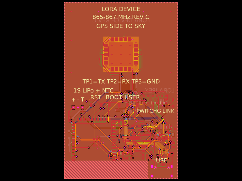 More from this authorgokul/lora-deviceA compact LoRa/GNSS device PCB integrating an SX1262 radio, GNSS module, USB/UART interface, 1.5 µH inductor, LiPo battery connector with NTC, and supporting passives.
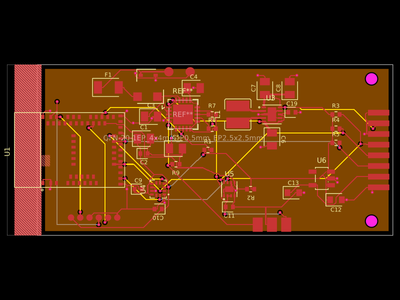 Similar packagemohan-bee/fitness-bandA 4-layer BLE wearable mainboard with Li-ion charging/protection, 3.3/1.8 V power regulation, motion and battery sensing, plus a folded 2-layer flex sensor board carrying MAX30102 optical and TMP117 temperature sensors.
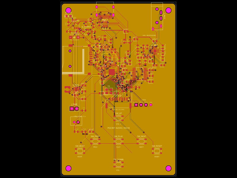 Discover something newDevesh36/pocket-audio-playerA portable, rechargeable microSD audio player built around an RP2040, SPI flash, USB‑C charging/power management, LCD/button controls, PCM5102A I²S DAC, and TPA6132A headphone amplifier in a 3D‑printed enclosure.