gokul/flex-led-wristband
A flexible, rechargeable touch wristband PCB with MCP73831 Li-ion charging, switched 3.0 V regulation, ATtiny402 control, TTP223 capacitive touch sensing, and six charlieplexed red LEDs plus power/charge indicators.
- Version
- 0.0.3
- License
- unset
- Stars
- 0
BRINGUP.txt
PROTOTYPE BRING-UP — NOT YET PERFORMED
1. Inspect bare flex, coverlay contacts, drill and stiffener alignment. Reject torn, creased, delaminated or exposed unintended copper. Check assembly IC pin1 and LED cathodes against assembly.svg and assembly-orientation.csv.
2. Without battery or charger attached, measure BAT/GND and VCC/GND for shorts; verify switch OFF opens2-3 and ON closes2-3. Confirm polarity of battery leads and protected pack.
3. Apply a current-limited bench supply at BAT+/BAT- (start3.7 V, current limit10 mA, increase only after investigating any limit). Verify OFF isolates VSW, ON gives approximately3.0 V on VCC. Verify correct power LED and abnormal heating absent. Test across protected pack's intended voltage range; do not overdischarge a real cell.
4. Program using target-powered 3 V compatible UPDI. Keep PA0 as UPDI. Use 5 MHz or another datasheet-permitted clock and appropriate brown-out. Firmware needed: PA6=A, PA7=B, PA1=C via330 ohm each; PA2=touch. Blank A/B/C to inputs without pullups before each source/sink pair. Current path contains660 ohm. Validate all six LEDs individually, then multiplex; observe no ghosting and measure current.
5. Allow touch IC power-up calibration without touching. Test through actual enclosure dielectric at all battery voltages. Check false activations, moisture sensitivity and response with battery mounted. A5 mm pad and maximum-sensitivity configuration are not a tested user interface.
6. With switch OFF and a suitable protected cell rated for>=50 mA charge, connect regulated5 V to charge contacts. Check charge current, 4.2 V regulation, taper/termination, STAT indication and restart. Check cell/charger temperature under normal conditions; do not conduct destructive battery tests. Verify no reverse battery connection or external VCC backfeed.
7. Verify protection cutoff against chosen pack datasheet. Attach pack flat in rigid insulated strap-supported enclosure, strain-relieve wires, prevent skin contact with exposed conductors. Charge off wrist. Perform mechanical/bend durability and insulation testing for intended use before wear. Do not crease flex or place battery load on it.
This procedure is a validation plan, not a claim that measurements were performed. Firmware, enclosure and battery selection are external to the PCB manufacturing release.
Related Packages
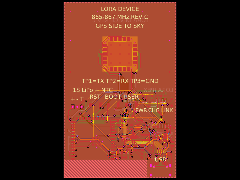 More from this authorgokul/lora-deviceA compact LoRa/GNSS device PCB integrating an SX1262 radio, GNSS module, USB/UART interface, 1.5 µH inductor, LiPo battery connector with NTC, and supporting passives.
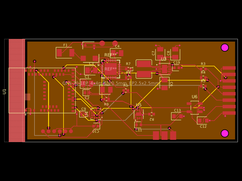 Similar packagemohan-bee/fitness-bandA 4-layer BLE wearable mainboard with Li-ion charging/protection, 3.3/1.8 V power regulation, motion and battery sensing, plus a folded 2-layer flex sensor board carrying MAX30102 optical and TMP117 temperature sensors.
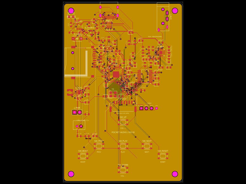 Discover something newDevesh36/pocket-audio-playerA portable, rechargeable microSD audio player built around an RP2040, SPI flash, USB‑C charging/power management, LCD/button controls, PCM5102A I²S DAC, and TPA6132A headphone amplifier in a 3D‑printed enclosure.