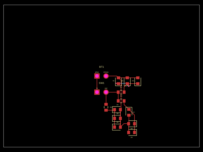
ekamresh/tscircuit_test_pcb
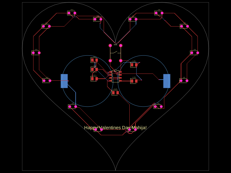
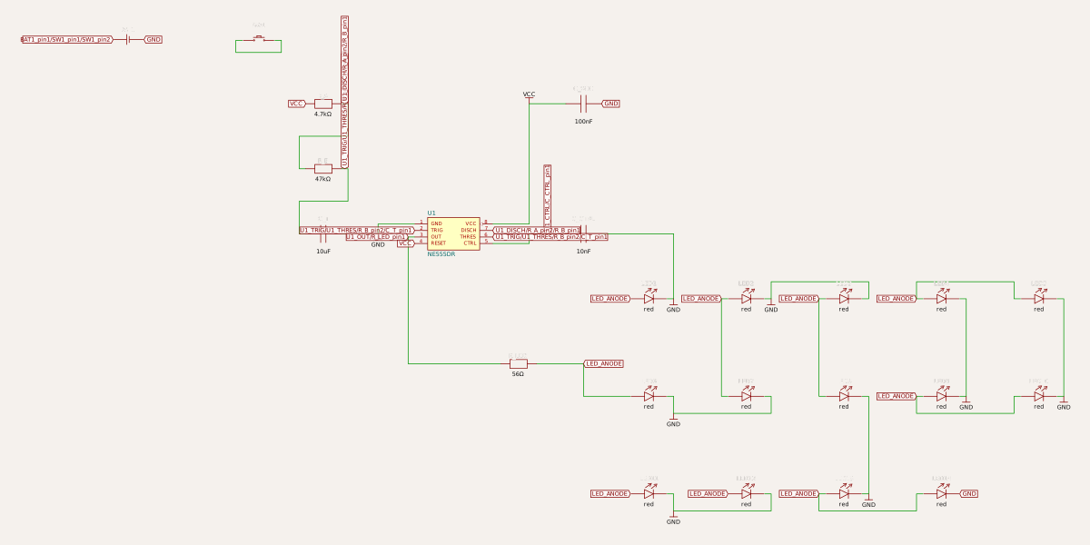
This code designs a battery-powered, heart-shaped circuit board featuring a NE555 timer configured as an astable multivibrator, driving 14 parallel red LEDs arranged around the heart's outline, powered by two series CR2032 coin cells, with power switching and silent silkscreen annotations.
- Version
- 1.0.0
- License
- unset
- Stars
- 0
index.circuit.tsx
PCB
Schematic
import React from "react"

// ---------------------------------------------------------------------------
// Heart-shaped 555 timer LED blinker  -  "Happy Valentines Day Mahija!"
// ---------------------------------------------------------------------------
// Power:    2 x CR2032 in series (6V) on the BACK of the board, soft-power
//           via a tactile pushbutton.  CR2032s give ~30 mA continuous which
//           is exactly what we need.
//
// Circuit:  Classic NE555 astable multivibrator
//   f  = 1.44 / ((Ra + 2*Rb) * C)
//   Ra = 4.7k, Rb = 47k, C = 10uF  ->  ~1.46 Hz, ~52% duty cycle
//
// LEDs:     14 x 5 mm through-hole red LEDs around the heart border, all
//           wired in parallel through ONE shared 56 ohm 0805 current-limit
//           resistor.  At 6V supply with the 555 sourcing ~45 mA, each LED
//           sees ~3 mA average -> bright enough for an indoor display
//           without taxing the chip or the cells.
// ---------------------------------------------------------------------------

// --- Heart-shaped board outline -------------------------------------------
// Parametric heart curve (Eugene Beutel, 1909):
//   x(t) = 16 sin^3(t)
//   y(t) = 13 cos(t) - 5 cos(2t) - 2 cos(3t) - cos(4t)
const HEART_SCALE = 2.5 // mm per unit  ->  ~80 mm wide x ~72 mm tall
const HEART_Y_OFFSET = 2 // shift up so the centroid sits near (0,0)
const HEART_OUTLINE = Array.from({ length: 96 }, (_, i) => {
  const t = (i / 96) * Math.PI * 2
  const x = 16 * Math.sin(t) ** 3
  const y =
    13 * Math.cos(t) -
    5 * Math.cos(2 * t) -
    2 * Math.cos(3 * t) -
    Math.cos(4 * t)
  return { x: x * HEART_SCALE, y: y * HEART_SCALE + HEART_Y_OFFSET }
})

// --- LED ring positions ----------------------------------------------------
// 14 hand-picked t-values, mirrored across the y-axis.  They sweep both
// lobes from upper-shoulder down past the bottom point, but skip:
//   - the cleavage (small t) where the heart curve dips inward, and
//   - the very bottom point (t near pi) where there is no room.
const LED_INSET = 0.85
const LED_TS = [
  0.65, 0.96, 1.27, 1.58, 1.88, 2.19, 2.5,
  3.783, 4.093, 4.403, 4.703, 5.013, 5.323, 5.633,
]
const LED_POSITIONS = LED_TS.map((t) => {
  const x = 16 * Math.sin(t) ** 3
  const y =
    13 * Math.cos(t) -
    5 * Math.cos(2 * t) -
    2 * Math.cos(3 * t) -
    Math.cos(4 * t)
  return {
    x: x * HEART_SCALE * LED_INSET,
    y: y * HEART_SCALE * LED_INSET + HEART_Y_OFFSET,
  }
})
const NUM_LEDS = LED_POSITIONS.length

// 5 mm through-hole LED footprint: 2.54 mm lead pitch, 1 mm plated holes
const LED_TH_FOOTPRINT = "led_tht_p2.54mm_pw1mm_ph1mm"

// --- Battery holder footprint ---------------------------------------------
// Custom footprint approximating a horizontal dual-CR2032 holder
// (e.g. Keystone 1042 / MPD BC-2032-2).  The two cells sit side-by-side
// inside a plastic body about 50 mm x 22 mm; the cells are wired in series
// internally, so the PCB only sees a +6 V terminal and a GND terminal at
// the far ends of the body.  We mount it on the BACK of the board so the
// front face stays clean for the silkscreen love note.
const DualCoinCellFootprint = (
  <footprint>
    {/* + terminal (positive end of cell 1) */}
    <smtpad
      pcbX={-22}
      pcbY={0}
      shape="rect"
      width={3}
      height={6}
      portHints={["1", "pos", "BAT_POS"]}
    />
    {/* GND terminal (negative end of cell 2) */}
    <smtpad
      pcbX={22}
      pcbY={0}
      shape="rect"
      width={3}
      height={6}
      portHints={["2", "neg", "BAT_NEG"]}
    />
    {/* Silkscreen outline of the two coin cells.  No courtyard rect: the
        holder lives on the BACK of the board, alone, so it cannot collide
        with anything on the front. */}
    <silkscreencircle pcbX={-12} pcbY={0} radius={11} />
    <silkscreencircle pcbX={12} pcbY={0} radius={11} />
  </footprint>
)

export default () => (
  <board
    outline={HEART_OUTLINE}
    solderMaskColor="purple"
    silkscreenColor="white"
    layers={2}
  >
    {/* ----------------------------------------------------------------- */}
    {/* NE555 timer (SOIC-8)                                              */}
    {/* ----------------------------------------------------------------- */}
    <chip
      name="U1"
      footprint="soic8"
      manufacturerPartNumber="NE555DR"
      pinLabels={{
        pin1: "GND",
        pin2: "TRIG",
        pin3: "OUT",
        pin4: "RESET",
        pin5: "CTRL",
        pin6: "THRES",
        pin7: "DISCH",
        pin8: "VCC",
      }}
      pinAttributes={{
        VCC: { requiresPower: true },
        GND: { requiresGround: true },
        RESET: { mustBeConnected: true },
      }}
      pcbX={0}
      pcbY={0}
      schX={0}
      schY={0}
    />

    {/* ----------------------------------------------------------------- */}
    {/* 555 timing network                                                */}
    {/*   Ra (R_A) : VCC   -> DISCH                                       */}
    {/*   Rb (R_B) : DISCH -> THRES (= TRIG)                              */}
    {/*   Ct       : THRES -> GND                                         */}
    {/* ----------------------------------------------------------------- */}
    <resistor
      name="R_A"
      resistance="4.7k"
      footprint="0805"
      pcbX={-9}
      pcbY={7}
      schX={-4}
      schY={4}
    />
    <resistor
      name="R_B"
      resistance="47k"
      footprint="0805"
      pcbX={-9}
      pcbY={3}
      schX={-4}
      schY={2}
    />
    <capacitor
      name="C_T"
      capacitance="10uF"
      footprint="0805"
      pcbX={-9}
      pcbY={-1}
      schX={-4}
      schY={0}
    />

    {/* CTRL pin bypass capacitor (datasheet recommended) */}
    <capacitor
      name="C_CTRL"
      capacitance="10nF"
      footprint="0805"
      pcbX={8}
      pcbY={-2}
      schX={4}
      schY={0}
    />

    {/* VCC decoupling capacitor right next to pin 8 */}
    <capacitor
      name="C_VCC"
      capacitance="100nF"
      footprint="0805"
      pcbX={8}
      pcbY={5}
      schX={4}
      schY={4}
    />

    {/* ----------------------------------------------------------------- */}
    {/* Single shared LED current-limit resistor                          */}
    {/*   OUT -> R_LED -> LED_ANODE rail (drives all 14 LEDs in parallel) */}
    {/*                                                                   */}
    {/*   Vsupply  = 6 V (2x CR2032)                                      */}
    {/*   V_OH(loaded) ~ 4.5 V at 50 mA out                               */}
    {/*   V_LED    ~ 2.0 V (red, low current)                             */}
    {/*   I_total  = (4.5 - 2.0) / 56  ~  45 mA                           */}
    {/*   Per LED  ~ 3.2 mA average -> nicely visible indoors             */}
    {/* ----------------------------------------------------------------- */}
    <resistor
      name="R_LED"
      resistance="56"
      footprint="0805"
      pcbX={0}
      pcbY={-7}
      schX={2}
      schY={-4}
    />

    {/* ----------------------------------------------------------------- */}
    {/* LED ring  -  14 x 5 mm THT red LEDs, all anodes commoned to       */}
    {/* LED_ANODE rail and all cathodes to GND.                           */}
    {/* ----------------------------------------------------------------- */}
    {LED_POSITIONS.map((p, i) => {
      const idx = i + 1
      return (
        <led
          key={idx}
          name={`LED${idx}`}
          color="red"
          footprint={LED_TH_FOOTPRINT}
          pcbX={p.x}
          pcbY={p.y}
          schX={6 + ((idx - 1) % 5) * 3}
          schY={-2 - Math.floor((idx - 1) / 5) * 3}
        />
      )
    })}

    {/* ----------------------------------------------------------------- */}
    {/* Power: 2x CR2032 in series (6 V) on the BACK of the board         */}
    {/* ----------------------------------------------------------------- */}
    <battery
      name="BAT1"
      voltage="6V"
      capacity="225mAh"
      footprint={DualCoinCellFootprint}
      layer="bottom"
      pcbX={0}
      pcbY={-2}
      schX={-10}
      schY={6}
    />

    {/* ----------------------------------------------------------------- */}
    {/* Power switch.  Tactile pushbutton at the top of the heart -       */}
    {/* press to blink (or solder a wire across pins 1-3 for "always on", */}
    {/* or replace with a slide switch for latching power).               */}
    {/* ----------------------------------------------------------------- */}
    <pushbutton
      name="SW1"
      footprint="pushbutton"
      pcbX={0}
      pcbY={10}
      schX={-6}
      schY={6}
    />

    {/* ----------------------------------------------------------------- */}
    {/* Silkscreen love note                                              */}
    {/* ----------------------------------------------------------------- */}
    <silkscreentext
      text="Happy Valentines Day Mahija!"
      fontSize={2}
      pcbX={0}
      pcbY={-22}
    />

    {/* ================================================================= */}
    {/* Connectivity                                                      */}
    {/* ================================================================= */}

    {/* --- Power rails ------------------------------------------------- */}
    {/* Battery + -> switch -> VCC rail.  Battery - -> GND rail.          */}
    {/* Pushbutton has 4 pads: pin1+pin2 are one terminal, pin3+pin4 the  */}
    {/* other.  Tie both pads on each side.                               */}
    <trace from=".BAT1 > .pin1" to=".SW1 > .pin1" />
    <trace from=".BAT1 > .pin1" to=".SW1 > .pin2" />
    <trace from=".SW1 > .pin3" to="net.VCC" />
    <trace from=".SW1 > .pin4" to="net.VCC" />
    <trace from=".BAT1 > .pin2" to="net.GND" />

    {/* --- 555 power and reset ----------------------------------------- */}
    <trace from=".U1 > .VCC" to="net.VCC" />
    <trace from=".U1 > .GND" to="net.GND" />
    <trace from=".U1 > .RESET" to="net.VCC" />

    {/* --- Decoupling -------------------------------------------------- */}
    <trace from=".C_VCC > .pin1" to="net.VCC" />
    <trace from=".C_VCC > .pin2" to="net.GND" />
    <trace from=".C_CTRL > .pin1" to=".U1 > .CTRL" />
    <trace from=".C_CTRL > .pin2" to="net.GND" />

    {/* --- Astable timing network -------------------------------------- */}
    <trace from=".R_A > .pin1" to="net.VCC" />
    <trace from=".R_A > .pin2" to=".U1 > .DISCH" />
    <trace from=".R_B > .pin1" to=".U1 > .DISCH" />
    <trace from=".R_B > .pin2" to=".U1 > .THRES" />
    <trace from=".U1 > .THRES" to=".U1 > .TRIG" />
    <trace from=".C_T > .pin1" to=".U1 > .THRES" />
    <trace from=".C_T > .pin2" to="net.GND" />

    {/* --- Single shared current-limit resistor ------------------------ */}
    <trace from=".U1 > .OUT" to=".R_LED > .pin1" />
    <trace from=".R_LED > .pin2" to="net.LED_ANODE" />

    {/* --- LED ring : all anodes -> LED_ANODE, all cathodes -> GND ----- */}
    {LED_POSITIONS.map((_, i) => {
      const idx = i + 1
      return (
        <React.Fragment key={`net-${idx}`}>
          <trace from={`.LED${idx} > .pin1`} to="net.LED_ANODE" />
          <trace from={`.LED${idx} > .pin2`} to="net.GND" />
        </React.Fragment>
      )
    })}
  </board>
)