arnavk-09/two-test-points
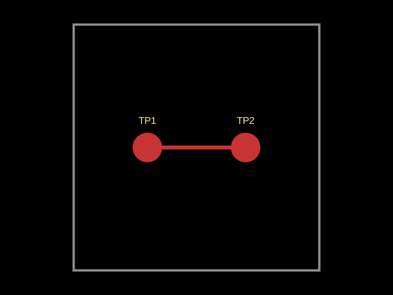
This code constructs a 10mm by 10mm PCB with two test points connected by a trace.
- Version
- 0.0.2
- License
- unset
- Stars
- 0
dist/schematic.svg
PCB

Schematic

<svg xmlns="http://www.w3.org/2000/svg" width="1200" height="600" style="background-color: rgb(245, 241, 237)" data-real-to-screen-transform="matrix(NaN,NaN,NaN,NaN,NaN,NaN)" data-software-used-string="@tscircuit/core@0.0.1025"><style>
              .boundary { fill: rgb(245, 241, 237); }
              .schematic-boundary { fill: none; stroke: #fff; }
              .component { fill: none; stroke: rgb(132, 0, 0); }
              .chip { fill: rgb(255, 255, 194); stroke: rgb(132, 0, 0); }
              .component-pin { fill: none; stroke: rgb(132, 0, 0); }
              /* Basic per-trace hover fallback */
              .trace:hover {
                filter: invert(1);
              }
              .trace:hover .trace-crossing-outline {
                opacity: 0;
              }
              .trace:hover .trace-junction {
                filter: invert(1);
              }
              /* Net-hover highlighting: when a trace or its overlays are hovered,
                 invert color for all traces (base + overlays) sharing the same
                 subcircuit connectivity key. Also hide crossing outline during hover. */

              .text { font-family: sans-serif; fill: rgb(0, 150, 0); }
              .pin-number { fill: rgb(169, 0, 0); }
              .port-label { fill: rgb(0, 100, 100); }
              .component-name { fill: rgb(0, 100, 100); }
            </style><rect class="boundary" x="0" y="0" width="1200" height="600"/></svg>
Related Packages
 More from this authorArnavK-09/WA 10mm x 10mm PCB with a 1kΩ 0402 resistor and a 1000pF 0402 capacitor connected in series.
 Similar packageseveibar/two-test-pointsA 10mm x 10mm circuit board with two test points connected by a trace.
 Discover something newimrishabh18/pcbgolfThis code defines detailed PCB footprints for various electronic components (such as resistors, capacitors, connectors, ICs, LEDs, and via/hole patterns), as well as associated metadata (pin mappings, CAD models, labels) for a circuit design, enabling precise rendering and integration into a PCB layout in a React-based schematic editor.