abse/museair-usb
USB-C–powered ESP32-C3 controller board with AP63203 buck conversion, AP2112K 3.3V regulation, I²C SEN62 sensor interface, status LED, buttons, UART/I²C headers, and extensive decoupling.
- Version
- 0.5.7
- License
- unset
- Stars
- 0
docs/DISPLAY-AUDIO-IMPLEMENTATION.md
# Local display/audio revision

The main source is `index.circuit.tsx`; the enclosure assembly remains independent in `assembly.circuit.tsx`. This revision has not been published.

All new soldered parts are on the PCB top and retain exact JLC/EasyEDA imported footprints and component CAD. Main additions: ZTS6216 top-port analog MEMS microphone (C481302), MCP6001 preamp (C116490), MAX98357A I²S amplifier (C910544), JST GH-2 speaker header (C189893), TCA9534A control expander (C206010), and AFC24 10-pin display connector (C262680).

Microphone: filtered 3.3 V supply, 20 nF C0G AC coupling, 1 MΩ input bias, gain 51, approximately 1.1 V reference, 5.1 kΩ / 10 nF ADC filter. It feeds GPIO0 / ADC1. The microphone-adjacent 100 nF bypass is C0G; Class II ceramic capacitors are kept away from the microphone per manufacturer guidance. The lid has a dedicated acoustic port and removable gasket aligned with the microphone. ADC noise, enclosure sound pickup and gain must be tested in hardware; this is a voice-oriented analog path, not a validated high-fidelity audio design.

Speaker: GPIO5/6/7 provide BCLK / WS / DIN. The MAX98357A is set to 6 dB gain and its enable has a 1 kΩ pulldown so it stays muted at expander reset. Its differential output goes to J7; **neither speaker terminal is ground**. The selected enclosure speaker envelope is Adafruit #1890, 28 mm diameter × 4.5 mm deep, 8 Ω, **0.25 W rated / 0.5 W maximum**. The amplifier can exceed that rating: playback firmware must limit RMS output to approximately 1.41 V across the 8 Ω load for 0.25 W, with suitable transient margin. Firmware limiting is not implemented in this hardware revision. The supplier sells this speaker with bare wires, so order a supplier-crimped GHR-02V-S / GH-2 lead assembly; do not assume a matching plug is included.

The speaker sits on the enclosure's right wall, with an internal cradle and grille. The harness rises around the PCB edge, crosses above the board and plugs into top-side J7. The display is on the opposite wall from the sensor air ports. Lid, PCB and sensor-holder fasteners preserve top service access; the lid is a separate hideable CAD group.

Programming remains the existing SH-3 connector compatible with tscircuit/standard-jst-programmer, powered separately through USB-C. Current JLCPCB C160403 product data reports out of stock; procurement readiness is blocked until that retained connector is sourced. Catalog snapshots for other parts are not reserved inventory.

Nominal CAD checks do not establish production tolerances, acoustic sealing, flex fatigue, speaker retention, thermal performance, RF performance or firmware operation. Prototype these before fabrication release.

Builds use guarded, reviewed copper corrections in `scripts/display-audio-routing-repairs.json`, followed by ground-pour regeneration and design checks. Changing pad placement or autorouter output deliberately invalidates those corrections and requires a fresh review. Native KiCad and its exported Gerbers are the fabrication authority. Do not assume a hosted tscircuit build runs the npm postbuild correction; validate hosted output separately before any later publication.

Use a regulated 5 V USB supply with at least 1 A capacity for the sensor, ESP radio peaks, display backlight and speaker. USB-C remains power only. Peak draw and brownout margin need a prototype test.
Related Packages
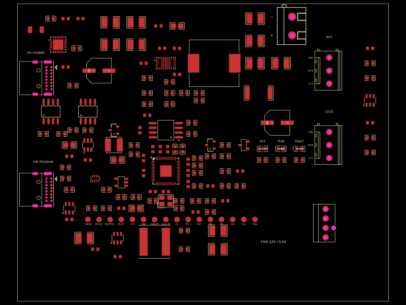 More from this authorabse/dual-usb-peltier-assemblyA USB‑C PD Peltier controller PCB combining RP2040 control, adjustable buck‑boost TEC power, temperature sensing, fan regulation, USB programming, protection, status LEDs, and external accessory hardware.
 Similar packagemohan-bee/esp32-c3This hardware design integrates an ESP32-C3 microcontroller, a USB-C connector, a power management IC (AP2112-3.3V regulator), a USB-to-Serial converter (CH340C), several resistors, capacitors, and user-accessible headers to facilitate USB communication, power regulation, and general I/O interfacing.
 Discover something new0hmX/mt41k512m8da-107-it-p-fanoutThis code defines the physical footprint, routing, and layout configuration for a DDR3 memory module using surface-mount pads, vias, and copper traces on a printed circuit board (PCB).