abse/museair-usb
USB-C–powered ESP32-C3 controller board with AP63203 buck conversion, AP2112K 3.3V regulation, I²C SEN62 sensor interface, status LED, buttons, UART/I²C headers, and extensive decoupling.
- Version
- 0.5.7
- License
- unset
- Stars
- 0
CHAT-CONTEXT.md
## Prototype fabrication roundup and live schematic cleanup — 2026-10-09

Website right-click Run Style Analysis rerun after publication:0 issues. All71 components/test points have explanatory notes; seven sheets. C3/C12 schematic positions grouped inside POWER frame, removing sheet-boundary warning; no electrical/PCB geometry/copper changes. Typecheck/build, circuit/routing, CLI netlist/pin/placement/source/Gerber shorts, switch datasheet-pin audit and native DRC pass0 errors/violations/unconnected. Native BOM/CPL/Gerbers audited and hashes current. Bare PCB prototype fabrication ready; assembled-board procurement needs J6 C160403 confirmation (catalog25 overseas, pre-sale0). J7 C177225 catalog pre-purchase availability recorded; none reserved. L1 catalog2A/3.2A/78mohm confirms nominal margin for600mA intended rail; manufacturer PDF unavailable. Firmware/hardware/rail/airflow/RF tests remain prototype work. Review docs/PROTOTYPE-FABRICATION-REVIEW.md, validation/prototype-fabrication-roundup.json; publication receipt validation/prototype-roundup-publication.json. Source and checked schematic preview published; no new hosted build queued for schematic-only cleanup; assembly unchanged.

## Direct manufacturer speaker connection published — 2026-10-09

Real J7 replaced with imported Molex53261-0271 / C177225 at PCB(15.2,24.3), rotation0. TPG2 shifted to(20.4,25). Original speaker51021-0200 plug connects directly, red27±1mm and black23±1mm cut/recrimped stock leads; no adapter. Checked routing and native DRC zero errors.19 independent assembly groups. Hosted build 4596719a-eab7-43b3-bf0f-fe791f58d6f3 passed. Main preview remains index, assembly separate. Receipt validation/direct-speaker-publication.json. Physical fit/RF untested; older disconnected notes superseded.

## Direct speaker connection repair pending publication — 2026-10-09

User requested fixing disconnected speaker. Real J7 now exact importedMolex53261-0271 / JLC C177225 at(15.2,24.3), rotation0; factoryMolex51021-0200 directly mates, manufacturer drawings confirm. TPG2 shifted(20.4,25); no enclosure or board pose changes. Shortened stock wiresred27±1mm/black23±1mm; originalhousing and standardcrimpcontacts, noadapter. NominalCAD clearance and3mm release pass; nativeDRC0 violations/unconnected. Fullbuild/manufacturing/hostedverification inprogress. Historicaldisconnected notes below superseded only upon completion.

## Rotated connector and cut-lead assembly published — 2026-10-09

Published index.circuit.tsx with J7 rotated180° and checked copper, plus separate19-group assembly with12±1mm cut-and-recrimped stock speaker lead and original Molex plug. No custom adapter. Hosted build 20561682-5597-4280-a4f1-f7b1387a1bc9 passed; files verified. Main preview remains index. Speaker plug remains DISCONNECTED: PCB JST GH is incompatible and matching Molex PCB header is still needed. Receipt validation/rotated-speaker-publication.json. Earlier local-only notes are historical.

## Stock lead shortened by cutting — 2026-10-09

User explicitly authorized cutting the cable, no custom hardware. Modeled12±1mm free lead with small service bow; original Molex51021 housing retained, new standard compatible crimp contacts/tool required. No adapter or custom short-lead SKU. Catalog stock length152±5mm remains documented. PCB J7 remains incompatible JST GH; plug is disconnected pending matching Molex PCB header. Earlier no-user-crimp restriction superseded for this authorized cable modification. Local only.

## Manufacturer-only speaker correction — 2026-10-09

User rejected custom adapter and cable modification: removed custom Molex-to-GH adapter, restored unmodified CMS-28588N-L152A factory152±5mm cable and included51021-0200 plug. Assembly19groups; speaker plug intentionally DISCONNECTED because real PCB J7 is JST GH and cannot mate. Matching Molex PicoBlade PCB header sourcing/import/routing is outstanding; do not claim buildable connector compatibility. No PCB changes this turn. Drawing-derived CAD remains illustrative, not exact manufacturer STEP. Earlier12mm/25mm custom specifications and BOM superseded. Local only, not published.

## Short speaker lead — 2026-10-09

User requested removing excess cable with a little slack. Assembly speaker lead now12±1mm, direct small service bow, no152mm storage coils; adapter stays25±2mm. Same speaker body/PCB/enclosure. Procurement requires custom MUSEAIR-SPEAKER-SHORT-01, supplier-shortened/reterminated base CMS-28588N-L152A; standard catalog lead remains152±5mm. Do not claim a stocked short-lead SKU or user solder/crimp requirement. Nominal cable clearance checked; physical sample still required. Local only, not published. Earlier long-lead instructions are superseded.

## Speaker connector turned toward speaker — 2026-10-09

J7 rotated 180° at unchanged PCB(13.5,24.8), world(-22.3,13.5,38.6); cable opening now assembly −X / PCB +Y toward speaker wall. Both speaker output tracks and conflicting R7 route rerouted; remaining reviewed copper unchanged. Guarded routing replay refreshed and full source build/postbuild checked. Circuit/routing checks zero errors; native KiCad9 DRC zero violations/unconnected; fabrication files regenerated and audited. Twenty-group assembly uses retained imported JLC CAD, rotated exact J7 mesh and refreshed checked PCB mesh. Custom adapter shortened from45±2 to25±2mm free lead with direct outward-side rise beside support ledge; both wires separated, factory152±5mm retained. 23 mesh pairs and 3mm plug release pass; top-service and sensor harness checks pass. Local screenshots preview/sourced-speaker/. This revision is local, NOT published; prior successful publication below is historical. Physical fit/RF still untested; stock/custom adapter procurement limits unchanged. Reports validation/speaker-routing-review.json, sourced-speaker-fit.json, speaker-wire-clearance.json. Python CAD tools restored under /workspace/.cad-python, use PYTHONPATH=/workspace/.cad-python; no fresh component CAD download needed.

## Real speaker-side J7 relocation and routed board — 2026-10-07

User authorized real-board routing. Prior assembly-only placement was inside antenna keepout and is superseded. J7 now PCB(13.5,24.8), world(-22.3,13.5,38.6), opening towards board interior. Antenna keepout retained (J7 pad gap0.100mm); R7 moved to(14.5,11) for plug release access. Six trace paths rerouted, other checked copper retained; guarded replay scripts/apply-speaker-routing.mjs + speaker-routing-reviewed.json. Typecheck/build, all checks/routing, CLI netlist/pins/placement/source/Gerber shorts, native KiCad9.0.2 DRC0violations/0unconnected and independent production audit pass; fabrication outputs regenerated. Extra PCB bitmap short scan remains unavailable in pinnedCLI. Exact website schematic analyzer0issues. Main PCB GLB and20-group assembly match real board. Factory conductors each152mm, service turns below speaker-side corner with no red/black overlap; custom adapter45±2mm free lead. Nominal23clearancepairs and3mm plug release pass. See validation/speaker-routing-review.json and speaker-plug-access.json. Speaker/frame/terminal leads remain close below antenna: RF and physical sample testing still required, no interference-free claim. Stock shortages/customadapter quote remain unresolved. Published with successful hosted build ab4681f5-e1e3-434d-b86f-2716f2be1768 on 2026-10-09; checked board and 20-group assembly verified. Receipt validation/speaker-publication.json. Snapshots preview/sourced-speaker/.

## Local speaker-side J7 placement proposal — 2026-10-07

User requested implementing concept in assembly with real dimensions. Actual imported J7 body moved to(-28,17,38.6)mm in assembly only, rotated180deg; index electrical connector/copper unchanged pending separate reroute. Factory152±5mm wires retained as under-PCB corner turns, custom adapter30±2mm free leads routes around support ledge. Case external dimensions unchanged. Nominal23collisionpairs and component/cable checks pass; real sample/RF untested. See validation/sourced-speaker-fit.json and mechanical/SPEAKER-ASSEMBLY.md. No publication.

## Current local sourced-speaker revision — 2026-10-07

CMS-28588N-L152A selected: DigiKey $5.16, 667 stock observed, 8Ω/2W, Ø28×5.5mm manufacturer drawing (distributor lists5.8; reserve6mm). Factory152±5mm lead with Molex51021 plug; separate custom preassembled51047-to-JSTGHR02V adapter,20±2mm free lead, needs quote/sample. Drawing-derived CAD and20-group assembly updated locally, no PCB electrical change, no purchase or publication. See mechanical/SPEAKER-ASSEMBLY.md; previews preview/sourced-speaker/. Older Adafruit0.25W statements are superseded. Physical fit/acoustics/limiter remain unverified.

## Raised ASK and assembly published — 7 October 2026

User explicitly authorized pushing both the new switch and assembly. Published to abse/museair-usb@0.5.7, hosted build 83639964-7c31-48ce-ba6f-a405111048e2 passed with exit0. Main index source contains SW1 C480275 / TS-1102S-B-H-B and checked copper matches local validation, zero error records. Assembly source and eighteen binary model assets verified; ASK_BUTTON_CAP is separate from REMOVABLE_TOP_LID and ENCLOSURE_BASE. Main preview stays index.circuit.tsx; assembly remains assembly.circuit.tsx with both dist/assembly/circuit.json and dist/assembly.circuit/circuit.json artifacts. BOM/CPL/Gerber ZIP/native checked board and audit reports uploaded and verified. Receipt: validation/tall-ask-publication.json. Link: https://tscircuit.com/abse/museair-usb#3d . Prior “not published” notes refer to the earlier local stage and are superseded. Physical snap retention/overtravel/fit remain untested.

## Raised ASK implementation completed locally — 7 October 2026

User accepted C480275 / TS-1102S-B-H-B, 7.5 mm height, and requested a separately hideable enclosure cap. User also explicitly requested manufacturer datasheet checks for every switch. ASK diagram internally joins 1–2 and 3–4; these pairs are ASK and GND respectively. RESET/BOOT C720477 are two-terminal normally-open switches with no duplicated common pair, mapped EN/GND and BOOT/GND. Saved both datasheets; check-switch-pinouts.mjs checks source nets, pads and internal connection metadata. R17 moved to(7.8,-3.5), R18 to(6,-13.2), ASK center unchanged(0,-8). CAD family supplier model was 4.5mm tall; documented derivative maps body to3.30 and actuator to7.50mm while preserving imported XY footprint. Cap separated as ASK_BUTTON_CAP with showButton prop, 18 assembly CAD groups. Nominal cap/lid clearance across±0.20mm height and0.25mm stroke passed; physical snap retention/overtravel untested. Local implementation not published. Main TypeScript and assembly builds pass, zero circuit/routing errors, Gerber scan no shorts, native DRC zero violations/zero unconnected. Final manufacturing files regenerated; 173 trace paths and via/pad/port geometries reproduced by guarded routing replay. Extra PCB bitmap scan unavailable due layerCanvas.getContext error. Design verification passes; overall procurement check fails known C160403 stock and C480275 overseas pre-purchase. Review validation/tall-ask-button-review.json. Snapshots preview/tall-ask-button/. Docs/research/ask-button/IMPLEMENTATION.md has details.

## Taller ASK switch preferred — 7 October 2026

User rejected4.3mm as too short. Preferred height candidate now XKB TS-1102S-B-H-B / JLC C480275: total7.5mm, body3.3mm, round3.5mm actuator,160gf,0.25mm nominal travel, top-actuatedSMT. Manufacturer PDF visually inspected and saved. JLC priceabout$0.0524, overseas/presale stock listed; not reserved assembly inventory. Actuator topZ46.1 is1.1mm into lid45..47 and0.9mm below outside; fits nominally in existing6.2mm hole. Same shell dimensions possible with redesigned retained cap and no-preload/overtravel stops. Larger6x6 body/12x5.9 recommended pad envelope needs moving R17/R18 and rerouting/revalidation. No circuit/CAD/publication changes yet. docs/research/ask-button/PROPOSAL.md taller section supersedes4.3mm recommendation.

## Raised ASK button research — 7 October 2026

User requests a raised switch under the exterior plastic cap without increasing enclosure dimensions. Recommended candidate C&K PTS645SM43SMTR92LFS / JLC C221880: SMT6x6mm body,9mm terminal span,4.3±0.1mm total height,round3.5mm actuator,160gf momentarySPST-NO. JLC catalog about$0.2844, overseas stock/presale listed; not reserved assembly stock. Current2mm switch remains installed. New switch needs moving nearby R17/R18 and rerouting, and shortening/reworking cap stem with no-preload gap and real travel/overtravel stops. Candidate topZ42.9 vs lid underside45 leaves2.1mm nominal room; same enclosure80x56x44. Exact operating travel and total tolerance stack not verified. No implementation or publication for this search. Docs/research/ask-button/PROPOSAL.md and saved manufacturer PDF contain evidence and follow-up requirements.

## Electrical index display/audio publication — 7 October 2026

User explicitly authorized publishing the real electrical index too. Main `abse/museair-usb@0.5.7` now has the current71-component/seven-sheet index including MIC1 microphone/preamp, I2S amplifier/J7 speaker GH2 connector, and J8 display FPC connector/I2C controls. Matching exact JLC imports, models, reviewed routing scripts and cache uploaded; native checked board/BOM/CPL/Gerbers uploaded and bytes verified. Hosted build `43369553-802b-43db-8b6c-70724f715360 passed (exit0). Hosted pad placement equals validated local board. After hosted completion, checked local copper and PCB/schematic SVG installed and verified; final main circuit JSON equals validated local, zero error records. Main live preview selects index.circuit.tsx and contains MIC1/J7/J8 CAD. Separate latest17-group PCB-shift assembly source/models/artifacts preserved. Registry output briefly served stale records immediately after completion; refreshed verification passed. Receipt: validation/index-display-audio-publication.json. Link: https://tscircuit.com/abse/museair-usb#3d . Earlier statements that main index has not been published are superseded. Physical hardware/audio/RF/thermal checks and firmware remain unfinished; C160403 programmer header stock issue remains.

## Published PCB-shift assembly — 7 October 2026

User approved and requested pushing the latest assembly. Updated `assembly.circuit.tsx` and all17 dedicated CAD assets in the existing main `abse/museair-usb@0.5.7` project. Hosted build `823ddfae-5a2b-4d28-9c10-ae530ce0f1cc` passed with exit0,17 CAD groups and zero assembly error records. Main electrical source and checked main preview/artifacts preserved. The assembly includes +2.5mm PCB pose, near-flush rounded USB surround, shifted matching mounts/controls, opposite-wall speaker and adjusted harness/FPC. Full SH3 lead fit in the installed enclosure remains unverified; program bare board as previously planned. Receipt: validation/pcb-shift-publication.json. Link: https://tscircuit.com/abse/museair-usb . Earlier local/not-published status below is historical for this assembly.

## Local PCB shift toward USB-C — 7 October 2026

PCB assembly pose moves +2.5mm in X only; main electrical source and connector positions relative to PCB are unchanged. Board right edgeX37.5 gives0.5mm nominal inner-wall gap; USB socket faceX39.275,0.725mm behind overallX40 exterior and0.025mm behind integral lipX39.3 (nearly flush). Four internal PCB mounts/inserts/hardware follow the board. Two right lid-post centers move to(36.2,+/-25.7) to clear board corners; left lid posts unchanged. Mic opening/gasket, button and lightpipe shift with PCB; sensor/holder and speaker/display stay fixed. Sensor lead retains original under-board route and changes only upper tail,64.8mm bound route; GH2 top lead follows J7; exactly60mm display FPC retained with original3.6/3/2.5mm nominal bends and fixed panel position. BREP base/tool/PCB-envelope checks,23 mesh pairs, actual component/base contact checks and USB/sensor cable contact checks pass. Programming J6 has2.53mm to inner wall: actual SH3 cable insertion/bend envelope is NOT verified with enclosure installed. Program bare board as planned; do not promise assembled programming-cable access. Physical fit/tolerance/acoustics remain untested. Report validation/pcb-shift-fit.json; local screenshots preview/pcb-shift/. Not published.

## Local USB surround / opposite-wall speaker revision — 2026-10-07

User requested better USB-C exposure and a close-fitting integral enclosure opening rather than a square hole. Speaker and its grille/cradle moved to negative-X end wall; wire rerouted around left PCB edge. Overall80x56 envelope, display and flex, PCB/sensor positions unchanged. Integral rounded recessed surround has1.2mm face atX36.3,9.54x4.7mm rounded aperture (radius1.2), giving socket frontX36.775 nominal0.475mm projection from local lip. Socket is still3.225mm behind overallX40 wall; do not claim it protrudes beyond the entire enclosure. Socket/plug CAD clearance, one-solid base/tool checks and23 display/audio mesh pairs pass. Physical insertion/tolerance checks remain required. This revision is local, not published; preceding publication below is historical.

## Assembly publication — 2026-10-07

User authorized publishing the assembly file. Published the display/audio assembly in the existing main `abse/museair-usb@0.5.7` package. Hosted build `9b2f24ab-2e89-49af-8965-d357744d686b` completed with exit0,17 assembly CAD groups and zero error records. Assembly source and all17 model uploads verified. PCB upload uses geometry-preserving dedup/weld to fit registry payload limits; all204,521 triangles match the local model. Main hosted electrical source/artifacts and main PCB preview are preserved; the newer local electrical display/audio main board has not been published. Separate assembly file remains `assembly.circuit.tsx`. Report: `validation/display-audio-publication.json`. Link: https://tscircuit.com/abse/museair-usb . Earlier no-publish instructions below are historical for this assembly; do not infer permission to publish the local main electrical revision.

## Local top-service assembly draft — 7 October 2026, Europe/Tirane

## Latest local display/audio revision — 2026-10-07

User requested adding microphone, speaker connector and wide display flex connector, checking the tracks, then making an assembly and local images. **Do not publish this revision.** Earlier registry publication reports are historical; the last published main project remains the previous revision.

Implemented: top-side ZTS6216 analog top-port mic / MCP6001 gain51 to GPIO0 ADC1; MAX98357A I²S amplifier on GPIO5/6/7 and top-side JST GH-2 J7; BuyDisplay ER-TFT2.79-1 428x142 colour display, original indexed $3.89 candidate; top-side 10pin 0.5mm dual-contact AFC24 J8; native SPI GPIO18/19 with TCA9534A address0x38 controlling CS/DC/reset/amp enable on the shared100kHz I²C bus. Existing sensor, programmer, controls, LED, straps and separate ESP buck/sensor regulator connections are preserved. All65 SMT placements use exact JLC imports and component CAD. Seven schematic sheets have brief component explanations.

Main PCB stays `index.circuit.tsx`; the assembly remains `assembly.circuit.tsx`, with17 independent CAD groups and separately hideable base/lid. Display on positive-Y wall opposite sensor vents, 60mm factory flex with rounded U-turn/diagonal fold rising outside the PCB edge; speaker on right wall with a clean GH2 harness rising around the PCB edge. Integrated panel retaining ribs reserve0.25mm adhesive and clear the flex exit. Microphone lid hole at world(-0.7,12) matches the actual offset acoustic port. Four PCB mounting screws are internal; two low sensor-holder screws are accessible after unplugging/removing the PCB; four recessed external screws open only the separate lid.

`npm run build` passes using guarded reviewed copper corrections in `scripts/display-audio-routing-repairs.json`, applied by postbuild with regenerated pours and checks. Native KiCad9 DRC has0 violations and0 unconnected items; CLI netlist/pins/placement/source and Gerber shorts checks pass; BOM/CPL/drill/paste/Gerber audit passes (65 placements,28 unique JLC parts). Extra bitmap shorts checker is unavailable due layerCanvas.getContext. A J7 accessibility heuristic warning appears twice under different IDs; its actual internal mating cable is checked. The overall stock assertion fails because retained programmer header C160403 is currently out of stock; this is not an electrical failure. Do not assume a hosted tscircuit build runs npm postbuild; independently validate hosted output before any later publication.

Assembly build passes with17 groups. BREP one-piece-base/tool-access checks and23 mesh-clearance pairs pass; cable contacts are confined to intended PCB connectors. Physical tolerances, flex bending/insertion, acoustic seal, RF, thermals and audio remain untested. Speaker envelope is Adafruit1890,28mm diameter x4.5mm,8ohm,0.25W rated/0.5W maximum; factory GH2 crimp termination must be ordered because supplier speaker has bare wires. Playback firmware must cap RMS power to0.25W. Firmware is not implemented. Use a suitable regulated5V USB supply; peak current requires prototype validation.

Final local images: `preview/display-audio/desk.png`, `open-lid.png`, `board-connectors.png`, `internals.png`, `exploded.png`, `cables.png`; interactive viewer at `preview/display-audio/viewer/index.html` (serve over HTTP). Report: `validation/display-audio-review.json`; supplier/electrical details: `docs/research/display-audio/IMPLEMENTATION.md` and `DISPLAY-PROPOSAL.md`. Screen values are illustrative. Scratch staging `/workspace/museair-audio-revision` contains logs and baseline snapshots.


User requested real CAD matching the top-opening service concept and explicitly said not to push anything yet. Assembly now has separate ENCLOSURE_BASE and REMOVABLE_TOP_LID CAD IDs; walls/floor/PCB ledges are one base solid. Four internal PCB screws clamp to ledge inserts; two low holder feet use internal floor-insert screws reached after PCB removal. Upper holder screw tabs and external PCB/floor mounting screws are removed. The official sensor interface is a rear recessed socket adjacent to outlet; cable nose is aligned to manufacturer CAD opening near [4.45,-6.7,25.93] mm. Approximate bound route64mm, AWG26+ compatible GH6 guidance checked against datasheet p15. Fit/tool/cable checks and local assembly build pass; physical insert/fastener/mate/air performance untested. Source, matching PCB sensor CAD, portable generators and actual CAD snapshots are local only. See mechanical/HORIZONTAL-ASSEMBLY.md, mechanical/horizontal/top-service-fit-audit.json, sensor-cable-fit.json and preview/top-service/. Do not publish without new user authorization.

## Hosted routing timeout fixed — 7 October 2026, Europe/Tirane

Hosted build 4bd1136f-9873-4c1d-aa23-6c6523c6f005 failed at the 600000 ms PCB routing worker limit. Publishing the existing local .tscircuit/cache route files fixed it: hosted rebuild 071268d0-cf94-42ea-b6c5-7822c66f1975 completed successfully with exit 0 and no hosted error. Cache keys bind core version and routing input; changed PCB geometry invalidates them. Published main PCB circuit JSON matches the validated local board with zero error records; separate assembly has eight CAD groups and zero error records. See validation/host-timeout-rebuild.json and validation/horizontal-model-publication.json.

## Matching horizontal sensor CAD and outside screw access

PCB U3 now uses exactly the horizontal assembly sensor/carrier/tie geometry, with the same 4 mm sensor gap. PCB copper and holes are unchanged. Revised lid has outside-top PCB screws with captive nut clips; carrier screws enter from the bottom exterior. All ten screw axes pass the CAD tool-access check. See mechanical/HORIZONTAL-ASSEMBLY.md and mechanical/horizontal/external-fastener-audit.json. Physical print/fastener fit remains untested. Main preview stays the real PCB; assembly source remains separate.

## Latest preview decision

User requires main project 3D to show the real PCB and assembly.circuit.tsx to have its own file-level 3D tab. Main preview has been restored and verified equal to validated PCB. Assembly remains separate. The website currently supports only PCB/schematic per-file preview tabs; adding the requested file-level 3D tab requires a tscircuit.com frontend change. Do not redirect the main preview to the assembly. This supersedes the preview workaround below.

## Assembly 3D preview fix

The website file browser has only PCB/schematic per-file tabs. The main project 3D tab now selects assembly.circuit.tsx via tscircuit.config.json previewComponentPath; package main remains the PCB. The registry preview API requires the preserved dist/assembly.circuit/circuit.json alias for this filename. After rebuilding the assembly, refresh that alias from dist/assembly/circuit.json when publishing. validation/assembly-preview-selection.json verifies the live preview API returns the assembly and eight CAD models.

## Assembly example consolidated — 6 October 2026

`assembly.circuit.tsx` is the separate assembly example in the main abse/museair-usb package, with dedicated assembly-assets/. Its assembly-assets/ models are isolated from index.circuit.tsx and PCB imports. The assembly PCB model includes the v0.5.7 buck change. The separate assembly package remains a historical publication.

## ESP regulator heat revision — 6 October 2026

Local revision v0.5.7 replaces only ESP regulator U2 with AP63203WU-7 C780769 synchronous buck, L1 4.7uH C57269, C11 bootstrap 100nF and C12 additional 22uF output. Sensor U4 and programming pin maps remain unchanged. Estimated conversion loss is 0.11W rather than 0.51W at 300mA, assuming 90% efficiency; not measured. Inductor current/saturation/DCR manufacturer verification and bench thermal/ripple checks remain required before fabrication. See validation/esp-regulator-heat-design.json. Hosted v0.5.7 publication is tracked in validation/assembly-main-publication.json; older sections below are historical.

# MuseAir USB — project and conversation handoff

## Current revision update: plug-in programming (6 October 2026)

The user requested a solder-free programming connection and a realistic bare-board concept image. Local PCB revision v0.5.6 adds J6, JST SH 3-position 1.0 mm SM03B-SRSS-TB(LF)(SN), JLCPCB C160403, on the USB end of the board at source X −16, Y −30.5. Pin1 RX/GPIO20, pin2 GND, pin3 TX/GPIO21. Use a preterminated straight-through SH3-to-SH3 cable to standard-jst-programmer v0.8+ J5 (1 TX, 2 GND, 3 RX). J6 is populated during PCB assembly; no user soldering. J4 bare pads remain optional and unused for normal programming. Power target separately through USB-C; manual BOOT/RESET still required. Source now has 36 component annotations, 30 SMT placements / 15 unique JLC parts. Original v0.5.5 artifacts are historical and do not contain J6. Current validation state is in validation/programming-header-*.json/log and current native DRC; do not treat old handoff checksums as current revision checks. Physical fit, firmware and flashing remain untested. A new programming concept is in /workspace/museair-programming; Hosted board abse/museair-usb v0.5.6 and assembly abse/museair-usb-assembly v0.2.1 now include J6. Both hosted builds completed successfully on 6 October 2026. The hosted board circuit/PCB SVG were replaced after the hosted autoroute with the validated local clearance repairs and refilled ground pours; final hosted circuit is equal to local and contains zero error records. The assembly has 17 records with enclosure, 15 without, zero errors, and generated 3D previews. Publication receipts are in /workspace/museair-programming and /workspace/museair-horizontal/publication-verification.json.

The sections below retain historical handoff context. This revision update takes precedence for programming connector details.


Prepared on **6 October 2026**, Europe/Tirane. Current board package: **0.5.5**, hardware family **v0.5**. Original chat: **Explore pure-circuit AI gadgets**, ID `01a0fe55-d3da-7e13-9776-32ccba814796`.

## Start here

This file gives the next agent the complete working context. The companion [full chat transcript](docs/CHAT-TRANSCRIPT.md) preserves all retrievable user and user-facing assistant messages: **39 turns, 42 user messages, 188 assistant messages**, from the first gadget discussion through initial migration discovery. [Structured transcript](docs/CHAT-TRANSCRIPT.json) keeps message/turn IDs and original content. Private reasoning, system/developer instructions and raw command output are excluded; engineering results remain in `validation/`.

The thread reader records the user's original MuseMotion concept image as an image marker, without its pixels. The transcript documents this limitation. Available generated concept images and prompts are preserved under `docs/history/concept/`; they are historical illustrations, not fabrication evidence.

**Use the current design below.** The transcript intentionally retains older claims, sensor candidates, rejected directions, costs and permissions; they do not override later corrections. In particular, historical SPS30/SY-DS-AD wiring, battery concepts, antenna overhang, 8 mm sensor spacing and early cable recommendations are superseded.

## Current request and migration status

The user asked: “first move this whole project board to cloud env and add md make sure it iclude the whole chat context”, then clarified the destination as **“codex env”**. The requested Markdown and complete portable project have been prepared and cold-restored locally with all hashes verified. The Codex Cloud web interface is accessible and requires a GitHub repository. A new private **Abse2001/museair-usb** repository is being prepared as the source for a dedicated MuseAir cloud environment. **Cloud receipt/setup has not yet been confirmed**; see the later migration receipt if one exists.

Initial discovery exposed only local saved projects and no named environment in the CLI; the browser then exposed the Codex Cloud setup flow and the connected GitHub account Abse2001. The native `handoff_thread` tool cannot move its active chat to Codex Cloud, so this transfer uses the supported cloud environment setup instead of claiming a chat handoff. The original chat is preserved through the complete available transcript and current context file.
The local original is retained. Do not delete it as part of transfer. A source copy should be private, consistent with the existing private tscircuit publication. Do not copy authentication files, machine configuration, dependency caches or the machine-specific `node_modules` symlink. `docs/CLOUD-SETUP.md` explains setup and verification; `HANDOFF-MANIFEST.json` binds the transferred files by SHA-256.

## Intended product and user preferences

The user began by musing about AI gadgets made from pure circuits. That evolved into an ESP microcontroller board whose air-quality measurements an AI agent can access. The user explicitly accepted ESP Wi-Fi and Bluetooth, so the initial analog-only interpretation is no longer the hardware requirement.

“Muse” refers to the Meta AI agent the user had heard about. The goal is eventually **air → sensor → ESP → authenticated API bridge → agent**, with a phone used for Bluetooth provisioning or interaction. Early requests mentioned a screen/avatar and pressing a button to ask a question; the settled PCB has an ASK/PAIR button and status LED, with **no display**. Display/avatar interaction remains an optional future concept. The user corrected “BTC” as a transcription error: **there is no Bitcoin/BTC requirement**.

The user requested research into whether Meta/Muse supports this integration before promising it. Earlier assistant messages discussed Meta product claims; those historical links/claims have not been reverified during migration. **No supported direct Muse device/chat/avatar API was established or implemented.** Do not equate a general API bridge with a verified connection to the user's existing personal Muse.

The hardware is USB-C powered. Initial battery/circular-cell ideas were dropped; the current design has **no battery, charging circuit or boost converter**. The user asked for a small, cool board, exact JLCPCB/EasyEDA imports, tscircuit design/routing, in-stock parts, manufacturing checks including shorts, successful `tsci push`, a realistic sensor model, a 4 mm underside gap, an antenna wholly inside the board, four clean schematic sheets and short component explanations. Do not use AI image generation for subsequent board edits unless the user changes that instruction. CAD renderings and schematic/PCB previews are appropriate.

## Current hardware baseline

- PCB: **46 × 70 mm**, two copper layers, **1.6 mm FR4**, 1 oz copper; black solder mask in source.
- Controller U1: **ESP32-C3-WROOM-02-N4**, JLC **C2934560**, printed antenna; Wi-Fi and BLE hardware.
- Input J1: **TYPE-C-31-M-12**, **C165948**, USB-C **power only**. CC1 and CC2 have separate 5.1 kΩ pull-downs. USB data pins are intentionally unused.
- U2 and U4: **AP2112K-3.3TRG1**, **C51118**. U2 supplies ESP `V3V3`; U4 independently supplies sensor `PM3V3`; both are always enabled from `USB5V`.
- Sensor U3: separately purchased **Sensirion SEN62-SIN-T**. Laser particulate sensing plus humidity and temperature: PM1, PM2.5, PM4 and PM10. **No CO₂ measurement.** Body nominal **55.2 × 25.6 × 21.3 mm**.
- Sensor connector J3: genuine **JST SM06B-GHS-TB(LF)(SN)**, JLC **C133065**, six contacts, GH family, 1.25 mm pitch, side entry. Exact imported copper/paste geometry retained. Footprint pins 7/8 are mechanical hold-down tabs, deliberately floating.
- SMT assembly: **29 top-side components, 14 unique JLC part numbers**. U3, cable, carrier, ties and fasteners are excluded from JLC SMT BOM/CPL and installed after reflow.

### Cable and electrical mapping

The SEN62 socket is ACES **51468-0064N-001**, compatible with JST **GHR-06V-S** cable housings. Use a six-wire **GH-to-GH** cable, AWG26, preferably at most 100 mm. The exact complete, currently purchasable cable SKU remains **unverified**. Prior photographs showed an assembled example (a SEN66 with the same family of connector), not proof of what a SEN62 shipment contains. Do not promise an included or preinstalled cable. The early Adafruit cable example must not be accepted without checking connector family and cavity mapping.

| J3 cavity | Sensor cavity | Signal |
|---|---|---|
| 1 | 1 | PM3V3, +3.3 V |
| 2 | 2 | GND |
| 3 | 3 | SDA, ESP GPIO1 |
| 4 | 4 | SCL, ESP GPIO3 |
| 5 | 5 | GND |
| 6 | 6 | PM3V3, +3.3 V |

Confirm all six one-to-one connections by continuity before applying power; mating fit and wire colors are insufficient. Connect/disconnect with USB removed. Pins 1/6 and 2/5 are respectively paired inside the sensor.

R8/R9 are 10 kΩ I²C pullups to the ESP rail. U4 has C4 10 µF input, C8/C10 22 µF each and C9 100 nF output bypass. U2 has C2 10 µF input and C3 22 µF output. C5 22 µF and C6 100 nF decouple the ESP near its supply pin. Preserve exact component identities and pin mapping.

Sensor operating supply is **3.15–3.6 V**, with ripple at its pins at most **100 mV peak-to-peak**. The recorded datasheet maximum steady measurement load is 90 mA, peak 190 mA for 2 ms under its stated conditions. The U4 worst-case steady estimate recorded in the project is approximately 0.18 W / 33 K rise using the datasheet thermal resistance; it is an estimate, not a measured result. U2 continuous maximum-transmit thermal margin is unestablished. Bench voltage, transient, ripple, cable-drop and thermal measurements remain necessary.

### Controls and programming

| Feature | Connection / behavior |
|---|---|
| ASK/PAIR SW1 | GPIO4; firmware action pending |
| Status LED D1 | GPIO10 through R10; firmware behavior pending |
| RESET SW2 | ESP EN |
| BOOT SW3 | GPIO9; normal boot pullup |
| Boot pullups | R5 GPIO8, R6 GPIO9, R7 GPIO2 |
| J4 bare contacts | 2 mm pitch: GND, 3V3, TX, RX, BOOT, EN |
| J5 bare contacts | GND, 3V3, SDA, SCL; optional I²C access |
| TPG1–3 | Ground probe points |

Use a **3.3 V logic UART adapter**, cross TX/RX, share GND, and leave adapter power disconnected. Power the board through USB-C. Hold BOOT, tap RESET, release BOOT to flash. J4/J5 intentionally have **no solder-paste apertures**. Use a stable 5 V USB supply rated at least 1 A for initial prototype testing.

## Mechanics and RF placement

The SEN62 has molded retention features, **no screw holes**. Never drill the sensor or invent a screw pattern on its housing. Four PCB holes attach an insulating carrier, not the sensor directly.

PCB top-view coordinates relative to center: **(−18,−24), (+18,−24), (−18,+19), (+18,+19) mm**. Holes: **Ø2.4 mm NPTH**, spacing **36 × 43 mm**, **Ø5.6 mm copper exclusions**. Sensor body XY center is **(0,−6)**.

The latest explicit user spacing is **4 mm between sensor housing rear face and PCB underside**. Earlier “touching the board” and 8 mm gap statements are superseded. Carrier post tops touch the underside. Carrier: **45.9 × 65.5 × 29.3 mm**, lower flange extends 3.75 mm beyond the board. Four nylon **M2 × 35** screws, nuts and washers attach it; two nylon ties retain the sensor at Y=−18/−6 through the carrier slots. Example tie: Panduit PLT2M-C, 2.5 × 1.1 × 203 mm; actual assembly fit/tension untested.

The detailed model uses official Sensirion STEP geometry, a derived retainer and illustrative tie paths, not a box placeholder. Interfering free-state snap toes were relieved for a guided cradle. Recorded CAD intersections with nominal/max sensor envelope and ties are zero; carrier BRep is valid. Physical print fit, shrinkage, cable clearance, airflow/recirculation and heat coupling remain untested. Keep inlet/outlet and antenna clear of cables and ties. Included vendor foam is an enclosure reference; no sealed enclosure was validated.

U1 PCB anchor is **(0,+21) mm**. Its full imported courtyard top is Y=34.458, **0.542 mm inside** the board edge at Y=35. The top band **X=−23..+23, Y=27.65..35 mm** is a top/bottom copper keepout. Nearby support parts were relocated and the PCB rerouted; all 114 original source pin/net assignments were preserved. The antenna does not stick beyond the board. FR4 remains beneath it; no RF cutout is included. Espressif recommends removing base FR4 around an internal antenna and sufficient enclosure clearance (15 mm recommendation); **wireless throughput/range with sensor, cable and enclosure installed is not physically verified**.

CAD coordinate caution: assembly files use PCB underside Z=0, top-view XY. Tscircuit circuit JSON uses PCB midpoint Z=0, underside Z=−0.8, U3 CAD pose `(0,−6,−0.8)` and a bottom-side Y-axis flip. Native KiCad bottom models use a different X-axis flip and a 0.085 mm model standoff. `sen62-assembly-native.step` and the U3 offset `(0,3.5,−0.085)` compensate it. Do not change CAD pose/flip/hole positions without repeating alignment checks.

## Schematic and source structure

`index.circuit.tsx` defines one physical PCB with four real named schematic sheets, shared global nets, manually arranged schematic symbols and explanatory `schematictext`:

1. **POWER** — USB-C and power rails.
2. **CONTROLLER** — ESP32, decoupling, reset and boot.
3. **SENSOR** — cable connector, sensor, I²C pullups and optional contacts.
4. **INTERFACES** — ASK, LED, UART flashing pads and ground probes.

All **35 components/test points** have brief functional notes. `schSheetName` assignments keep PCB coordinates independent of sheet membership; `schAutoLayoutEnabled={false}` preserves manual schematic placement. Global net names must continue to connect across sheets. The default CLI schematic SVG shows a single sheet; `scripts/make-preview.mjs` exports each sheet plus a combined stacked SVG.

| Path | Purpose |
|---|---|
| `index.circuit.tsx` | PCB, nets, placement, routing and four schematic sheets |
| `components/JLCParts.tsx` | Adapted exact JLC/EasyEDA footprints and models |
| `imports/` | Unchanged raw exact part imports |
| `components/SEN62.tsx` | Separate sensor, carrier drill pattern and CAD pose |
| `models/SEN62AssemblyModel.ts` | Embedded detailed GLB; large base64 line, do not print wholesale |
| `mechanical/` | Official STEP, derived carrier, native assembly, GLB/STL/OBJ, mesh data, dimensional drawings and clearance reports |
| `dist/index/` | Local generated circuit JSON and SVGs; raw KiCad export is not the manufacturing authority |
| `fabrication-review/` | Corrected native KiCad board/project and portable footprint library |
| `order/` | Checked Gerbers, BOM, CPL, cable/mounting instructions |
| `preview/`, `review.html` | Final manufacturing and schematic review views |
| `validation/` | Net/geometry/stock/provenance/publication evidence and hashes |
| `scripts/` | Build checks, native export repair, audits, model generation and packaging |
| `docs/history/` | Historical research, concept and prior-release evidence; not current ordering files |

## Build, validation and publication status

Last hardware verification/publication was **4 October 2026**. Migration adds documentation/archive only and does not reroute the circuit. Existing validated manufacturing hashes must remain intact.

Recorded passing evidence:

- TypeScript and local `tsci build` succeeded.
- `runAllChecks` and explicit routing checks: **zero findings**.
- `tsci check shorts`, **Gerber mode / all layers**: passed, no detected shorts.
- CLI netlist, pin specification, placement and source: passed.
- Corrected native KiCad DRC: **zero violations, zero unconnected items**.
- 29 SMT placements / 14 BOM lines, pad-net assignments, CPL origin/rotations, drills/NPTHs, paste and CAD pose independently audited.
- The final U1 note move was schematic-only; **1,130 electrical/PCB/CAD records were identical** to the previously CLI-checked snapshot. The report transparently records that applicability proof.
- Four sheets and 35 explanations verified locally and in the server-generated circuit.
- Native CAD alignment, detailed GLB and 4 mm spacing validated; physical tests not performed.

The extra `--mode pcb` bitmap shorts scan failed because of **`layerCanvas.getContext is not a function`** in the pinned CLI raster renderer; it is not a pass. Gerber-mode shorts and native DRC provide the completed checks. Do not hide that scope limit or repeat broad testing without a changed circuit or new concern.

Native export repair is essential: duplicate pad nets, native metadata, coalesced close same-net vias, bare-contact paste, bottom model and ground-zone refill are handled by `prepare-kicad.py`. It retains removed native wrappers until exit to avoid KiCad 10 SWIG object-lifetime errors. Old guarded route-vertex corrections remain in the script, but **this release required none** (`clearance_vertex_corrections: []`). Final manufacturing files come from the corrected native board, not raw tscircuit export or registry copper preview.

Private registry: **https://tscircuit.com/abse/museair-usb**, owner `abse`, latest verified package **0.5.5**. Published with `tsci push --private --include-dist --compress`. The final archive upload timed out in the CLI, but readback confirmed **all 25 files saved**. All **18 source files matched**, server build completed **2026-10-04T13:21:31.398Z**, no server circuit errors, PCB/schematic/3D previews generated. Legacy `display_status=pending` was stale and not the active pipeline status. Server regenerated three dist files; those differ from uploaded local dist by design. Final local manufacturing files remain authoritative. Publication report is `validation/tscircuit-publication.json`.

Stock was refreshed **4 October 2026**, enough orderable JLC inventory for five boards. **Stock is not reserved and is historical on 6 October**; recheck before quotation/order. No purchase or supplier message was sent. The cable remains unresolved. Historical JLC quotation approval questions were not answered; do not infer authorization to message JLC or order from this cloud-transfer request.

## Exact assembly BOM

The authoritative CSV is `order/bom-jlcpcb.csv`:

| References | JLC part | Function / value |
|---|---|---|
| U1 | C2934560 | ESP32-C3-WROOM-02-N4 |
| J1 | C165948 | TYPE-C-31-M-12 |
| R1, R2 | C23186 | 5.1 kΩ USB-C CC pull-downs |
| C1 | C28323 | 1 µF 0805 |
| U2, U4 | C51118 | AP2112K-3.3 |
| C2, C4 | C15850 | 10 µF |
| C3, C5, C8, C10 | C45783 | 22 µF |
| R3–R9 | C25804 | 10 kΩ |
| SW1–SW3 | C720477 | TS-1088-AR02016 |
| C6, C9 | C14663 | 100 nF |
| C7 | C15849 | 1 µF 0603 |
| J3 | C133065 | Genuine JST GH-6 SMT side-entry |
| R10 | C21190 | 1 kΩ LED resistor |
| D1 | **C2297** | KT-0805G green LED |

The LED is **C2297**, not C22973. A mistaken auxiliary inventory lookup of C22973 was corrected before the final stock report; preserve the exact BOM/import part.

## Conversation evolution and superseded choices

1. Brainstormed analog circuit-only creatures and gadgets. User asked for more ideas, then room-air sensing accessible to an AI, initially without a display.
2. Clarified Muse/Meta AI, not an imaginary AI name. User asked for integration research, a sensor-bearing board, Wi-Fi/Bluetooth/phone/API access and optionally an avatar screen. “BTC” was corrected away.
3. Developed an AI concept poster resembling the user's MuseMotion V1 presentation. The poster is illustrative; the user then explicitly requested tscircuit/routing and no more image generation.
4. Settled on USB-C power. Initial compact SPS30-connected PCB was about 46 × 54 mm. User repeatedly objected to representing only a connector when the real sensor/model could be included.
5. Checked exact library footprints/imports. SPS30 could not be directly imported through available EasyEDA/tsci searches; preferred a real import or a matching connector if no usable footprint existed.
6. Explored lower-price laser options at Amazon/JLC. APM10/SY-DS-AD and PMS variants were screened. User temporarily chose **SY-DS-AD C3020625**, producing hardware v0.4 with a custom model/mount. Its pin-2 datasheet wording and supplier mechanical assembly required confirmation; no supplier request/order was sent. These files are historical.
7. User allowed buying the sensor separately if cheaper/similarly priced on Amazon and asked for good price/reviews. PMS5003 Amazon offers had differing ratings and high shipping/import totals for the then-selected Albania delivery setting. Those price/rating figures are dated research, not current recommendations.
8. User requested **DigiKey and Mouser**. SEN62 became the selected lower-price documented sensor: recorded **€17.40 / 645 stock** at Mouser Europe, **$20.42 / 96 stock** at DigiKey at the time; shipping/taxes/cable extra, customer reviews not verified.
9. User preferred a sensor cable with plugs. Photos showed a SEN66 example plus a GH-family cable illustration. Clarified factory sensor socket versus separately purchased cable; no included/preplugged cable was established.
10. Revised to **SEN62**, 3.3 V I²C, genuine GH-6 board connector, dedicated U4 regulator, matching four-hole carrier, larger 46 × 70 mm PCB. Published 0.5.1; user requested shorts and other checks, then readiness and push verification. 0.5.2 server build succeeded.
11. User requested a realistic sensor shape and underside contact, challenged the intentional gap, then explicitly chose **4 mm**. Official detailed CAD/derived carrier/ties replaced the placeholder; carrier posts meet the PCB while sensor stays 4 mm below. Published 0.5.3.
12. User moved the ESP antenna inside, requested cleaner schematic sheets and brief component notes. Support parts moved/routing updated, four sheets/35 notes added, exact prior net mapping preserved. A final note overlap was corrected. Published and verified **0.5.5**; physical RF tests remain pending.
13. Latest request: transfer full project to a cloud environment and preserve the whole chat context. Documentation and verified archive are prepared; the user clarified Codex Cloud, and private GitHub-backed environment setup is underway.

## Work still required for a functioning device

- Verify an available complete GH-to-GH cable and one-to-one cavity map.
- Build the PCB and carrier; verify mechanical fit, USB access, cable routing, retention and unobstructed sensor airflow.
- Measure both 3.3 V rails during startup, sensing and Wi-Fi load; check sensor voltage/ripple and regulator temperature in the actual enclosure.
- Verify Wi-Fi/BLE range/throughput with sensor, cable and enclosure installed.
- Implement firmware: SEN62 I²C address **0x6B**, at most **100 kHz**, wait at least 100 ms after power, start measurement/read data-ready, validate CRC-8 polynomial 0x31/init 0xFF, retry busy/NACK and report warmup/invalid/stale status. No clock stretching is provided. Use the official SEN62 driver and correct commands.
- Implement phone/BLE provisioning, authenticated Wi-Fi telemetry and API/tool bridge. Expose measured quantities, units, timestamps, freshness and errors.
- Reverify Meta/Muse integration support and access. Direct chat initiation/official avatar animation were not established; do not promise them.

The current board is documented for a **small prototype fabrication order**, not a physically tested, production-ready or fully integrated plug-and-play gadget.

## Primary references and supporting files

- [Sensirion SEN62](https://sensirion.com/products/catalog/SEN62)
- [SEN6x datasheet](https://sensirion.com/media/documents/FAFC548D/693FBB15/PS_DS_SEN6x.pdf), recorded preliminary v0.92, December 2025
- [Mechanical/assembly guide](https://sensirion.com/media/documents/4C2A5D87/6A70A6FF/SEN6x_Mechanical_Design_and_Assembly_Guidelines.pdf), recorded v1.01, July 2026
- [JST GH](https://www.jst-mfg.com/product/pdf/eng/eGH.pdf)
- [AP2112](https://www.diodes.com/assets/Datasheets/AP2112.pdf)
- [ESP32-C3-WROOM-02 datasheet](https://www.espressif.com/sites/default/files/documentation/esp32-c3-wroom-02_datasheet_en.pdf)
- [Espressif antenna placement](https://docs.espressif.com/projects/esp-hardware-design-guidelines/en/latest/esp32c3/pcb-layout-design.html#general-principles-of-pcb-layout-for-modules-positioning-a-module-on-a-base-board)
- [Official SEN62 Arduino driver](https://github.com/Sensirion/arduino-i2c-sen62)
- [Codex Cloud environment setup](https://learn.chatgpt.com/docs/environments/cloud-environments)
- [Codex local/remote handoff scope](https://learn.chatgpt.com/docs/remote-connections#hand-off-a-chat-between-hosts)

Consult the full transcript for every request/response and historical research link. Consult reports/README for release evidence, and the manufacturing files for exact geometry. Do not overwrite audited files with older scratch scripts or treat a stale report as a fresh check.

## Local schematic style cleanup (2026-10-07; not published)
Ran tsci check schematic-placement; corrected all 23 capacitor orientation warnings and pin padding on U1/U4/U5/U6. Reframed microphone/speaker circuitry within A4; consistent seven sheet headers; moved overlapping per-component descriptions into bottom legends; tightened controller/power/display spacing. Typecheck passed, runAllSchematicChecks returns []; four optional trace-simplification suggestions retained because suggested moves disturb functional grouping. validation/schematic-style-cleanup.json and schematic-placement-review.txt record results. All non-schematic circuit JSON records, including PCB/electrical/copper, exactly unchanged. Updated preview/schematic-*.png/.svg and dist/index/schematic.svg. No publication performed. Source backup and render/merge helpers in /workspace/museair-sch-cleanup.

## Schematic publication requested (2026-10-07)
User authorized push. New source and checked schematic circuit/preview SVG uploaded and registry-preview equality verified at https://tscircuit.com/abse/museair-usb. Hosted build 1bb99d35-4051-41c1-9fc5-1273f434ab84 remained running >15 minutes, with no completed result; do not claim hosted build success. validation/schematic-publication.json records checked-preview publication with build pending. Background monitor /workspace/museair-sch-cleanup/monitor.py (nohup, log monitor.log) checks for completion and runs extras.py to verify build and restore audited copper/assembly and publish review reports; timeout ~1 hour. If failed, restores checked main preview and records errors. Explicit pending status conveyed to user.

## Website viewer style correction (2026-10-07; local, not pushed)
User pointed out website right-click Run Style Analysis. Reproduced in Chromium: @tscircuit/schematic-viewer@2.0.101 reports29 issues across7sheets; prior CLI checks were incomplete. Retrieved SAME browser analyzer from https://jscdn.tscircuit.com/@tscircuit/circuit-json-schematic-placement-analysis/latest/dist/browser.js to /workspace/museair-sch-cleanup/analyzer.mjs. Local corrected circuit now getIssues()=[] using exact website analyzer: widened U6 to2.53; vertical power/ground resistors,LED,RESET/BOOT; grouped capacitors; raised R7 pullup; shortened microphone bias/ground paths; removed overlapping MIC_DIV texts by spacing. schMaxTraceDistance=.5. Electrical/source and all PCB records preserved exactly by schematic-only merge. Typecheck pass. validation/schematic-style-cleanup.json includes analyzerSHA,29->0,notpublished. Source beforethispass=/workspace/museair-sch-cleanup/before-viewer.tsx and before-viewer.json. Helpers render.ts,output.mjs,viewer-analysis.mjs,browser-verify.mjs. Reviewed power/microphone/speaker/display rendered PNGs; previews all7 refreshed.
Previous hostedbuild1bb99d35-4051-41c1-9fc5-1273f434ab84 finished17:51UTC with user_code_job_timeout: Build timed out after30minutes. BackgroundmonitorPID25931 stopped while editing toprevent unintendedpublication ofcurrentdraft. Old checked preview previouslypublished remains live; new29->0cleanupnotpublished. No furtherbuildqueuedthisturn.

## Zero-issue schematic published (2026-10-07)
User authorized push. Uploaded corrected index.circuit.tsx, checked schematic-only merged dist/index/circuit.json, schematic SVGs and style review to existing abse/museair-usb@0.5.7. Registry source/preview equality verified. Opened LIVE https://tscircuit.com/abse/museair-usb#schematic in fresh Chromium and invoked right-click Run Style Analysis: "No style issues found." / ISSUES[]. Screenshot preview/schematic-live-zero-issues.png; receipt validation/schematic-publication.json. Typecheck pass. PCB/electrical/copper unchanged. No new hostedbuildqueued; previous timedoutbuild remains failed; do notclaim successful newhostedbuild. Publication helper /workspace/museair-sch-cleanup/push-zero-style.py; live UI verification verify-live-zero.mjs and live-zero.log.


## Compact insertable sensor base and PCB bracing (2026-10-09; local, not published)
Replaced tall carrier with 58x28.7mm, 2mm open frame, low guides, two flush original feet and two stock nylon ties. Sensor pose, 4mm PCB gap, board/copper, USB position, display and speaker unchanged. Three original air passages have integral base-wall collars; seals unchanged. Four PCB ledges connect to sidewalls with paired triangular webs, relieved around speaker and display flex. Holder uses two M2x4 screws/0.5mm washers into standard M2 hex nuts in captive floor pockets (0.6mm closed backing); PCB retains four internal M2x5 screws.
IMPORTANT installation: PCB absent/cables unplugged; load nuts, lower bare base at Y+7.8mm and slide forward; lower bare sensor at Y+12mm and slide forward; ONLY THEN install holder screws and ties. Reverse separately for removal; cannot lift tied sensor/base as one unit. `check-sensor-insertion.py` samples148poses perpart against actual case/speaker/display/frame meshes. CAD checks pass, not physical fit/strength/airseal validation. Assembly19groups rebuild succeeds with zero error records; source/embedded GLBs match. Snapshots preview/compact-sensor-holder/. Main electrical files and current PCB preview preserved. No publication this turn.


## Prototype push-in snap sensor base (2026-10-09; local, not published)
User asked to try push-in clicks. Added two low side cantilever arms to existing compact base, lead-in ramps, small0.8x0.8mm noses engaging the original sensor STEP recesses at Y-8.1/Z12.9, nominal0.3mm engagement. Arms0.7mm thick/1.9mm high/~12mm free span, highestZ13.7; release tabs widen overall58.2mm. User must slide sensor forward inside enclosure (not straight-down push); spread clips outward to release. Base retains twoM2x4 screws. Ties are optionalbackup, defaultshowTies=false. Assembly18defaultgroups plus optional19thtie group. Build/typecheck/errorrecords/embeddedassets pass; mainPCBmodel preserved. Finalstatic BREP and audio/cablechecks pass. Sensorinsertion test now checks rigidframe (`carrier-rigid.glb`) separately: intendedflexibleclipcontact during insertion is excluded, deformation/force NOTsimulated. This is a provisional mechanism requiring tolerance, snap-force, pullout/fatigue and vibration tests;0.3mmengagement is shallow. Sensirion guidev1.01pp9–10supports prototype snapfixtures, notapproval of thiscustomdesign. Snapshots preview/compact-sensor-holder/snap-{base,seated,close}.png. No publication.


## Upright base-rooted sensor clips (2026-10-10; local, not published)
User rejected corner return arms; replaced them with two short vertical clips rising directly from broad tapered base feet, rounded0.3mm roots,0.6mm flex web/2.6mm width, sloped tips and release pads. TipZ14.1, overall58.2mm width. Existing0.3mmengagement in manufacturer CAD recesses remains shallow; no real sensor/sourceCAD modifications, sourceSHA verified. Not supplier-approved retention interface. StaticBREP/23audio clearances/sensorharness pass; assemblybuild18defaultgroups/errorrecords0/embeddedGLBsmatch/typecheckpass. PCBmodelunchanged. Rigid-envelopepathcheck excludesintendedflexibleclipcontact; noelasticforce/fatigue/strengthvalidation. Insidecase use drop-and-slide; benchdownwardpush onlynominalunverified. Localrenders preview/compact-sensor-holder/upright-snap-{base,seated,close}.png. validation/upright-snap-holder-review.json. This supersedes horizontalcornerclip design; physicalfit andretentionneedprintedprototype.


## Upright snap assembly published (2026-10-10)
User explicitly authorized publication despite untested clip fit/strength. Published assembly.circuit.tsx (18 default groups, optional ties), matching .ts wrappers and binary .glb assets, both compiled preview aliases, current mechanics docs/checks/review. Compiled online preview uses verified relative GLB paths to avoid registry413size limit; local preview retains embeddeddata. All uploads retrieved and checked, mainindexsource/distindex/mainpreview unchanged. Localassemblybuild/typecheck pass; no hostedbuildqueued. Receipt validation/upright-snap-holder-publication.json. Link https://tscircuit.com/abse/museair-usb; open assembly.circuit.tsx and3D. Physicalretention stilluntested.


## Full-quality assembly PCB synchronized and published (2026-10-10)
UserreportedassemblyPCBdifferent/lowquality. Foundpriorpack.pydownsampledtextures168x256. Re-exportedcheckedindex directlywithcircuit-json-to-gltf boardTextureResolution2048/boardDrillQualityhigh, verifiedactualonlineindexPCB+CADrecordsexactlyequalexportsourcedata. sync-assembly-pcb.py preservesall65PCBcomponentmodels/materials/normals/positions, excludesonlyseparateU3; setsacceptedPCBpose. FreshreferenceandcombinedmechanicalPCBupdated. Texture2048x3117, nomipmap/downsamplingbakedin. prepare-horizontal-assembly.py removesresizing,preservesnormals, splitsPCB_JLC_COMPONENTS/PCB_BOARD_ARTWORKintoseparateassets underregistry4MiBpayloadlimit;19defaultCADgroups+optional20thties. Fullassemblybuild/typecheck/0errorrecords,23meshclearances andconnector/cablechecks pass. Verifiedsourcewrappers/binarydownloadedmodelsandtwopreviewaliasesuploaded; mainindex/mainpreviewpreserved;nohostedbuildqueued. Receipt validation/assembly-pcb-quality-publication.json. Snapshot preview/compact-sensor-holder/pcb-hq.png. DO NOT useold /workspace/museair-picoblade/pack.py whichresizestextures256. Currentworkflow exportsfreshindex, syncassemblyPCB, prepareassembly,build,uploadseparateGLBs+sourcewrappers+relativeCADpreviewURLs.


## Native PCB colors and single hide group (2026-10-10)
User requested matching native index 3D colors and one hideable PCB model. Supersedes prior CPU-export/split-artwork solution: actual native CadViewer GLTFExporter capture preserves original board/materials/65 component models; U3 stays separate. One PCB_COMPLETE CAD item uses gltfUrl with external verified geometry buffers and six lossless WebP textures at native1621x2468, no resampling. Embedded original per-component CAD IDs removed to prevent incorrect selection/hide targets. Same accepted board pose; geometry/cables/enclosure unchanged. 18defaultgroups plus optionalties. package-native-assembly-pcb.py records source/index hashes,65refs,pixel equality. Native world PCB reference takes precedence in enclosure generator; do not rerun superseded CPU appearance sync. Local assembly build/typecheck and23clearance/cableconnector checks pass. Imported PCB texture faces draw both sides to avoid face culling and retain the original alpha-blend setting; native texture colors retained via unlit face shading to prevent added glTF environment reflections; component materials are unchanged. Native viewer Hide PCB_COMPLETE was exercised successfully: all1085 PCB meshes disappear together, no browser errors; sensor/enclosure/hardware remain separate. Published source, verified external geometry/texture assets and both checked compiled aliases to the main project. Mainindexsource/distindex/defaultpreview preserved. Receipts validation/assembly-native-viewer.json and assembly-native-pcb-publication.json. Source and binary round-trip comparisons passed; localbuild/typecheck passed. Multipart upload for one texture reset ready_to_build=false; no hosted-build success claimed. Snapshots preview/compact-sensor-holder/pcb-native-grouped.png and pcb-native-hidden.png.


2026-10-10 lid revision: removed printed lightpipe from lid, empty hole now nominal3.0734mm for Bivar PLP1-200 clear purchased candidate. Manufacturer drawing checked; distributors blocked, stock/price unverified. Existing D1 green. Removed three front sensor seal rings embedded inside integral collars; three rear foam seals retained. Native PCB face uses lit shading again with specular/clearcoat suppressed, same black index mask, textures and65parts, one PCB_COMPLETE group. See docs/research/led-light-pipe/SELECTION.md.

2026-10-10 user reported PCB and USB-C too black: restored all original native material settings; only boardface double-sided flag differs from capture. No recoloring of real index while requested color is pending. USB-C J1 original silver metal materials identical to capture; separate molded USB cable grip black. Build/typecheck pass; native material comparison and actual viewer Hide PCB_COMPLETE pass, no browser errors. Original reflections make imported board lighter than suppressed-reflection revision; actual physical soldermask still black.

2026-10-10 USB-C black root cause: original native export has non-indexed multi-material primitive groups all referencing full POSITION400. This superimposes black over silver J1 and affects other models. Correct export indexes cloned nonindexed multimaterial geometries sequentially before GLTFExporter; preserve groups. package-native-assembly-pcb.py now rejects distinct-material primitives without distinct indices. No material recoloring or source footprints/positions changes.

Correct indexed export verified:64multimaterialmeshes corrected; all65parts originalvertexattributes/materials/nodeposes identical; groupspartitionfacesexactlyonce. Native fullres6textures losslessunchanged,8versionedindexedgeometrybuffers. Actualviewer close-up preview/usb-c-socket-fixed.png shows J1 silver shell/gold contacts/dark tongue; component material overrides none. Assemblybuild/typecheck/0errorrecords pass. Native capture now /workspace/museair-native-board/native-pcb-fixed.glb; older native-pcb.glb is broken export and packerrejectsit. SinglePCB_COMPLETE preserved.
Related Packages
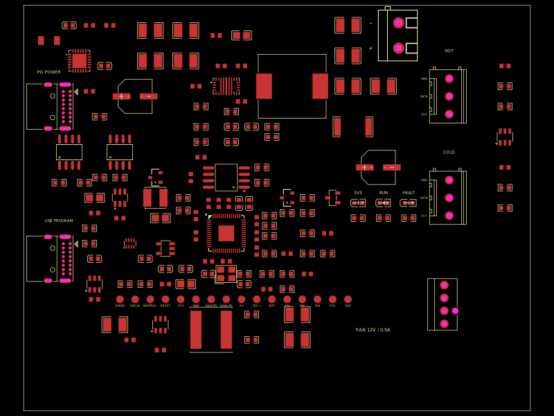 More from this authorabse/dual-usb-peltier-assemblyA USB‑C PD Peltier controller PCB combining RP2040 control, adjustable buck‑boost TEC power, temperature sensing, fan regulation, USB programming, protection, status LEDs, and external accessory hardware.
 Similar packagemohan-bee/esp32-c3This hardware design integrates an ESP32-C3 microcontroller, a USB-C connector, a power management IC (AP2112-3.3V regulator), a USB-to-Serial converter (CH340C), several resistors, capacitors, and user-accessible headers to facilitate USB communication, power regulation, and general I/O interfacing.
 Discover something new0hmX/mt41k512m8da-107-it-p-fanoutThis code defines the physical footprint, routing, and layout configuration for a DDR3 memory module using surface-mount pads, vias, and copper traces on a printed circuit board (PCB).