abse/gameboy-advance
A tscircuit package created by abse.
- Version
- 0.0.45
- License
- unset
- Stars
- 0
mechanical/fit-print/slide-display/README.txt
SLIDE-IN LCD MOUNT - R23 LOCAL FIT-PRINT CANDIDATE
For the selected bare ER-TFT035IPS-6, nominal83 x54.5 x2.3mm; no foam.
This replaces the previous TWO no-foam retainers with THREE printed parts.
The existing front shell is reused. The external bezel lip remains unchanged.

PRINT
1 lcd-slide-rail-left-print.stl
1 lcd-lock-lower-right-print.stl
1 lcd-lock-upper-right-print.stl
Or open display-slide-mount.3mf (millimetres; select printer/material and slice).
Use PETG; trial-print one set. Small compliant tabs may require removable
support underneath; inspect the slicer preview. Do not fuse support to the tabs.

HARDWARE
Reuse FOUR M2 x4 countersunk PH0 screws and the existing insert positions:
- Fixed left rail:2 screws at CAD XY(-43.6,-18),(-43.6,37.5).
- Lower connector-side retainer:1 screw at(49,-18).
- Upper connector-side retainer:1 screw at(62,39.8).
The former screw at(69,38) is unused in this revision; an existing insert may stay.
This does not implement the separate proposed M3 case-screw conversion.

ASSEMBLY WITH FLEX ALREADY CONNECTED
1 Remove AA cells and USB. Keep the front shell open, supported and face down.
  Install the fixed LEFT rail first with its two M2x4 screws.
2 Support the PCB clear of the mounting/screwdriver path. Keep button caps
  and PCB clear of the LCD insertion path. Unlock, seat and lock the FPC
  correctly before the sliding operation; never pull on the connected cable.
3 Keep the display's connector-side edge slightly toward the open rear:
  about2degrees tilt. Present the panel2mm to the right of its final position.
4 Slide LEFT2mm, into the fixed rail on the side far from the connector.
  The rail has small entry ramps on its compliant contacts. Do not force it.
5 Gently rotate the connector-side edge into the front bezel seat.
6 Fit the lower-right retainer from the open rear and start its M2x4 screw.
  Fit the upper-right retainer and start its M2x4 screw. Tighten gently and
  evenly against the printed mounting feet. Do not use screw torque to bend
  the LCD or make an incorrect panel thickness fit.
7 Confirm the panel cannot rattle, shows no pressure marks, and the flex has
  slack. Then finish the controls/PCB assembly and close the case carefully.

MOTION FILES
- display-slide-assembly.mp4:14-second assembly motion.
- display-slide-assembly.gif:looping version.
The animation uses the real revised mount meshes and sampled rigid-body
poses. Purple flex loop and green supported-PCB outline are schematic only;
the flex is shown connected throughout, but cable slack and bend radius are
NOT qualified by that drawing. Check these with the real panel before proceeding.

CHECKS
Three connected, watertight print meshes; no disconnected fragments.
82 hook/slide/seat samples and50 retainer-approach samples passed against
front shell and nominal panel. Intentional elastic spring-contact regions
are excluded from rigid interference tests; spring force is not measured.
39 final static neighbour checks passed against the nearby speaker, right
shoulder, speaker leads, flat-base button caps and the previous flex model.
The changed flex route itself is not physically or mechanically qualified.

REMAINING PHYSICAL CHECKS
The user measured2.5mm but requested retention of the2.3mm design: verify
actual fit carefully. Do not force a2.5mm panel into this nominal2.3mm mount.
Verify spring force/creep, frame contact,2mm cable slack, minimum flex radius,
access with the actual connected PCB, and absence of driver/stiffener bending.
This pack is a fit-print candidate; published PCB and enclosure are unchanged.
Related Packages
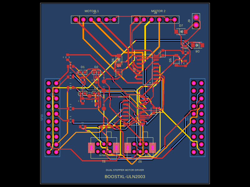 More from this authorabse/boostxl-uln2003This code defines a React component that models a through-hole or surface-mount LED with specified pin labels, footprint, silkscreen, and 3D CAD model for PCB layout.
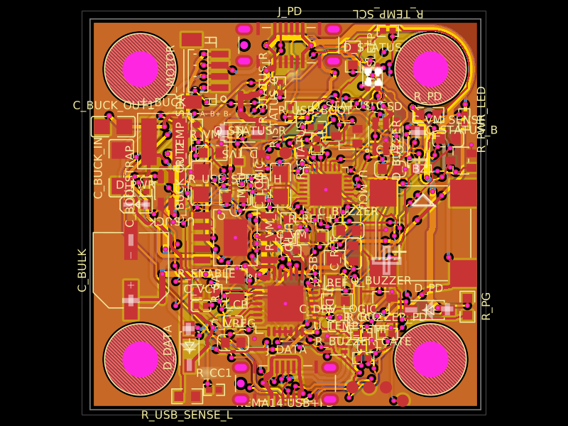 Discover something newAnasSarkiz/NEMA14_CH32X035G8U6A NEMA stepper motor is shown with proposed M3 screws/spacers, four wired motor leads and splices, and a JST SHR-04V-S connector.