abse/gameboy-advance
A tscircuit package created by abse.
- Version
- 0.0.45
- License
- unset
- Stars
- 0
mechanical/fit-print/rounded-caps/README.txt
ROUNDED BUTTON CAPS - LOCAL FIT-PRINT CANDIDATE
Seven replacements: A, B, X, Y, Start, Select and D-pad.
No PCB, switch-position or front-shell change is required for nominal CAD fit.

CHANGES
- Exposed face rises 3.0 mm above the existing 13.55 mm front surface
  (previous nominal protrusion 1.5 mm).
- Actuator cups extend to Z7.1; roofs remain at Z10.45 to avoid preloading.
  Nominal actuator engagement increases from about 1.4 to 3.2 mm.
- Face-button socket diameter 3.7 mm; entry flared to 4.3 mm.
- D-pad keeps four 4.8 mm clearance sockets so it can rock without pin binding.
- Round top edges: 1.0 mm radius on A/B/X/Y; 0.8 mm Start/Select and D-pad.
- A/B/X/Y exposed diameter is 10.0 mm. Start/Select diameter is 7.2 mm.
- D-pad exposed cross 25.4 mm tip-to-tip, 6.8 mm arm width; 0.7 mm rounded
  plan corners and 0.8 mm top-edge radii. A slimmer guide profile allows tilt.
- Retaining flanges keep caps captive under the shell, not glued or press-fit
  to the switch. Deeper sockets guide the actuators; they are not snap locks.
- The original central D-pad pivot and insulating pivot pad are retained.

PRINT
Use rounded-button-caps.3mf (all seven) or the *-rounded-print.stl files.
Files are in mm, crown down, cup openings up. This is a geometry-only 3MF;
select your printer and material in the slicer. Start with one PETG trial set,
0.4 mm nozzle / 0.2 mm layers. Confirm the 0.95 mm face-cup walls resolve.
Inspect supports at flange overhangs and rounded edges. Keep sockets clear of
support and elephant-foot bulges. The STEP files contain native solid CAD.
Do not print five sets until the first fit and return tests pass.

ASSEMBLY
1. Disconnect USB and remove AA cells. Open shells, support front assembly
   and release flex carefully before separating. Remove PCB only as needed
   for access; keep its insulating washers and M3 screws together.
2. Rear-load replacement caps into their matching openings. The X flange
   has a flat relief toward the display; do not mix it with A/B/Y.
3. Locate D-pad's four sockets over UP/DOWN/LEFT/RIGHT actuators and keep
   the central insulating pivot pad in place. Do not glue the cups.
4. Lower the PCB squarely so every actuator enters its socket. Tighten PCB
   screws gently and evenly; never use screws to force misaligned cups on.
5. Before closing, test each key and D-pad cardinal/diagonal press. Require
   free return and no wall scraping. Check again with case screws seated.
6. If a key sticks, reopen and inspect cup alignment, supports and guide
   surfaces. Do not force it or assume extra switch spring force will fix it.

CHECKED
- Seven native solids valid; seven meshes watertight and single-body.
- 48 front-shell motion poses: straight cap travel 0/0.15/0.4/0.45 mm and
  D-pad tilts through 3.22 degrees, including diagonal axes.
- 28 guide checks with 0.20 mm lateral offsets, excluding retaining stops.
- 162 switch/neighbour checks using the actual C3038675 supplier STEP and
  the no-foam display candidate. Pressed tests use a geometric 0.35 mm
  upper-stem relief envelope; this is NOT a measured switch travel rating.

REMAINING
These checks do not measure friction, surface roughness, print variation,
switch force, wear or actual travel. Physical one-set fit/return tests are
required. Test full press and release at low finger force, with the final
shell tightened. The published tscircuit assembly is not changed by this pack.
Related Packages
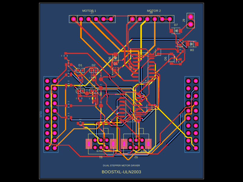 More from this authorabse/boostxl-uln2003This code defines a React component that models a through-hole or surface-mount LED with specified pin labels, footprint, silkscreen, and 3D CAD model for PCB layout.
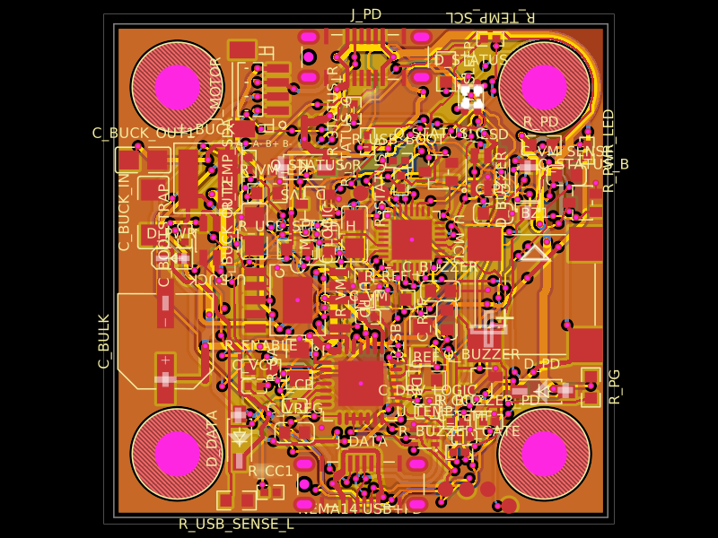 Discover something newAnasSarkiz/NEMA14_CH32X035G8U6A NEMA stepper motor is shown with proposed M3 screws/spacers, four wired motor leads and splices, and a JST SHR-04V-S connector.