abse/gameboy-advance
A tscircuit package created by abse.
- Version
- 0.0.45
- License
- unset
- Stars
- 0
mechanical/fit-print/nofoam-display/README.txt
NO-FOAM DISPLAY RETAINERS - LOCAL FIT-PRINT CANDIDATE
For ER-TFT035IPS-6 WITHOUT touch glass; nominal body 83 x 54.5 x 2.3 mm.

REPRINT ONLY:
1. lcd-retainer-lower-nofoam-print.stl
2. lcd-retainer-upper-nofoam-print.stl
Or open display-retainers-nofoam.3mf (both parts, mm).

Reuse the current front shell and its five M2 x 4 LCD screws/inserts.
No foam is used. Remove both old foam layers. No M3 case-screw conversion
is included in this display-mount change.

WHAT CHANGED
- The bare LCD sits 2.15 mm farther forward, against the existing inner bezel.
- Side guides provide nominal 0.15 mm clearance at the display edges.
- Six integral PETG spring tabs provide nominal 0.20 mm take-up.
- Hard stops limit rearward motion; mounting feet remain at their old height.
- Screw load bottoms on the printed mounting feet, not by crushing the glass.
- The existing external bezel lip remains: this is seated at the inner bezel,
  not a screen face level with the outside enclosure surface.

PRINT / FIT
Use PETG and start with 0.2 mm layers / 0.4 mm nozzle. Spring beams are
1.2 mm wide and 1.2 mm thick. Inspect slicer preview so each beam is formed
continuously. Supports may be needed below the raised tongues; remove them
without damaging the leaves. A successful export is not a verified slicer profile.
Print one pair first; do not print five sets before a physical fit test.

ASSEMBLY
1. Remove AA cells and USB. Open the case, support both halves, unlock and
   release the display flex before moving the screen.
2. Remove the five LCD screws and old upper/lower retainers. Remove foam.
3. Place the bare panel against the inner bezel; do not press the active face.
4. Install new lower and upper retainers using the same five M2 x 4 screws.
   Start all screws, then seat them gently and evenly against the printed feet.
5. Check that all six tabs contact the rear frame and that the panel cannot
   rattle. If bowed, pinched or requiring force, STOP and revise the fit.
   Do not compensate with extra screw torque.
6. Re-route the flex for the new panel position. Keep the driver and stiffener
   flat. Confirm the flex reaches the socket without tension or a sharp crease.
7. Reconnect the flex, inspect clearances, close gently and check image quality.
   Do not use if pressure marks, uneven backlight or glass stress appear.

CHECKS PERFORMED
Both meshes: watertight, one connected body, unchanged mounting feet.
No nominal intersection with existing front shell or nominal LCD outside the
intentional spring-tip take-up. Added-material collision checks passed against
sampled neighbouring speaker, X cap, D-pad, right shoulder, speaker leads and
existing flex model. These are static mesh checks, not physical qualification.

STILL REQUIRED
Measure actual panel thickness; inspect rear-frame contact regions; qualify
new flex routing, printed fit, spring force and PETG creep on the first unit.
Do not reuse the old all-component/assembly qualification reports as approval
for this new design. Original published board and enclosure remain unchanged.
Related Packages
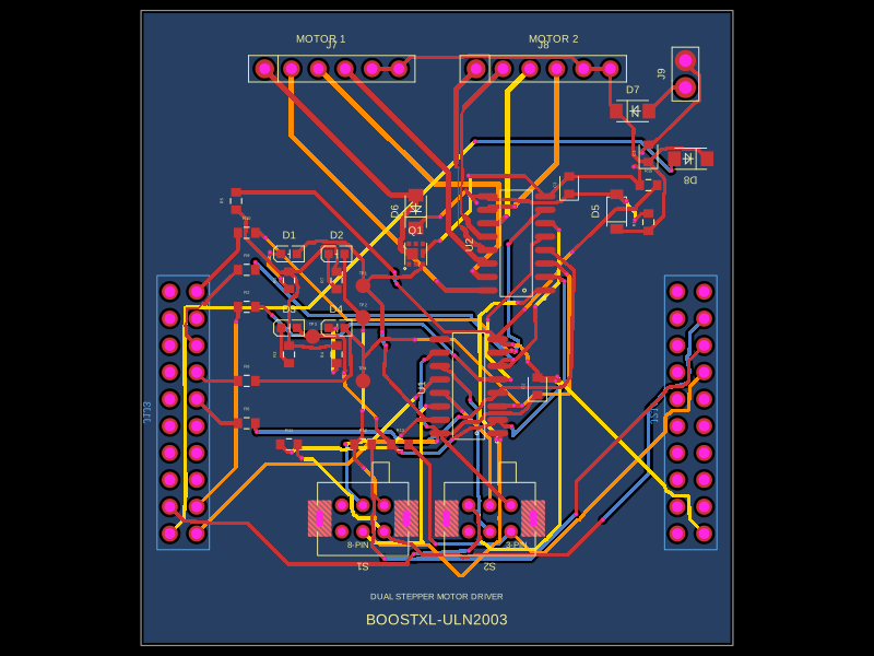 More from this authorabse/boostxl-uln2003This code defines a React component that models a through-hole or surface-mount LED with specified pin labels, footprint, silkscreen, and 3D CAD model for PCB layout.
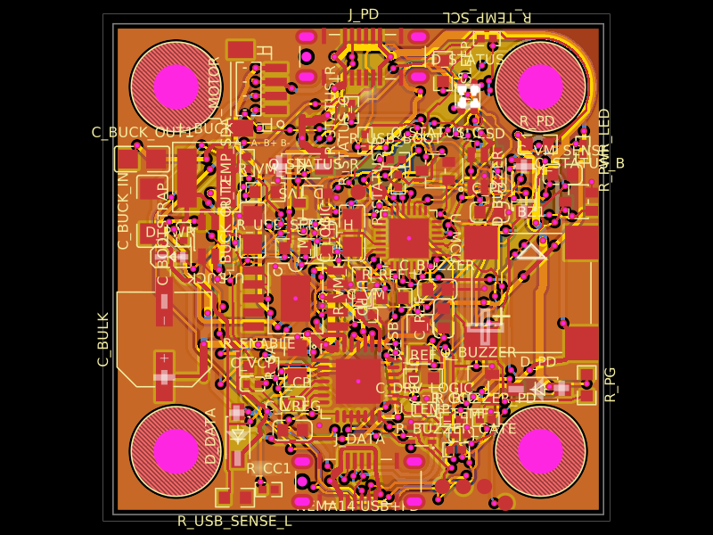 Discover something newAnasSarkiz/NEMA14_CH32X035G8U6A NEMA stepper motor is shown with proposed M3 screws/spacers, four wired motor leads and splices, and a JST SHR-04V-S connector.