abse/gameboy-advance
A tscircuit package created by abse.
- Version
- 0.0.45
- License
- unset
- Stars
- 0
mechanical/fit-print/flat-base-caps/README.txt
FLAT-BASE BUTTON CAPS - REVISION R22 / LOCAL FIT-PRINT CANDIDATE
This pack REPLACES the previous crown-down cap files.

CONTENTS / PRINT ORIENTATION
Six round caps (A/B/X/Y/Start/Select), one D-pad cap, one separate D-pad pivot.
Open flat-base-button-caps.3mf: all EIGHT parts are arranged upright, with
flat bottoms on the bed. STL units are millimetres; no automatic inversion.

THE LIP CHANGE YOU REQUESTED
The six round caps and D-pad flange now extend down to Z7.1, exactly level
with their actuator socket mouths. The upper retaining shoulder stays at
Z10.1. The new base is continuous; there is no elevated lip underside to
start printing in mid-air. Socket roofs remain at Z10.45 and button tops
at Z16.55: 3 mm nominal protrusion. Actuator engagement remains about3.2mm.
A/B/X/Y have rounded10mm tops; Start/Select7.2mm. X has a flat LCD-side relief.

D-PAD PIVOT
The old D-pad pivot projected below its sockets. Leaving it integral would
prevent the requested flat-base printing. It is now a separate3mm diameter,
7.1mm long printed pin. Insert its upper end1.5mm into the3.2mm diameter
centre socket underneath the D-pad before fitting the PCB. It is captive
between the D-pad and the existing central insulating pivot pad once assembled.
Do not omit that pad. No glue is specified. Check the pin seats fully and
rocks with the D-pad without rattling, binding or falling sideways.

ASSEMBLY
1. Remove AA cells and USB. Open the case and support both halves; release
   the display flex safely if separating them.
2. Rear-load the new round caps. Orient X's flat relief toward the display.
3. Fit the separate central pivot into the D-pad. Locate the four D-pad cups
   over the four switch actuators; retain the original insulating pivot pad.
4. Lower the PCB squarely. Never use PCB screws to force cups onto switches.
5. Test all cardinal and diagonal D-pad presses and each round button. Then
   test again with the enclosure screws seated. Require free return.

PRINT NOTES
Use the supplied upright orientation. Start with one PETG trial set,
0.4mm nozzle and0.2mm layers. A small bridge remains over each socket roof;
inspect the slicer's bridge preview. Do not put non-removable support inside
the blind sockets. The broad flat lip supports itself from the first layer.
Keep first-layer elephant foot out of socket mouths and moving guides.
Native STEP solids, STLs, parametric generator and geometry checks are included.

CHECKS
- Eight valid native solids; eight watertight, single-body print meshes.
- All eight have planar first-layer contact; no disconnected mesh fragments.
-48 front-shell motion poses, including0.45mm cap travel and3.22degree D-pad tilts.
-28 guide-clearance checks with0.20mm lateral offsets (retaining stops excluded).
-162 supplier switch / neighbour checks, including the no-foam display parts.
Pressed switch checks use geometric stem relief, not a measured travel rating.

Print fit, friction, return force, pivot seating and wear still require one
physical trial set. No guarantee of support-free slicing or friction-free
physical operation is implied. The published PCB/assembly has not been changed.
Related Packages
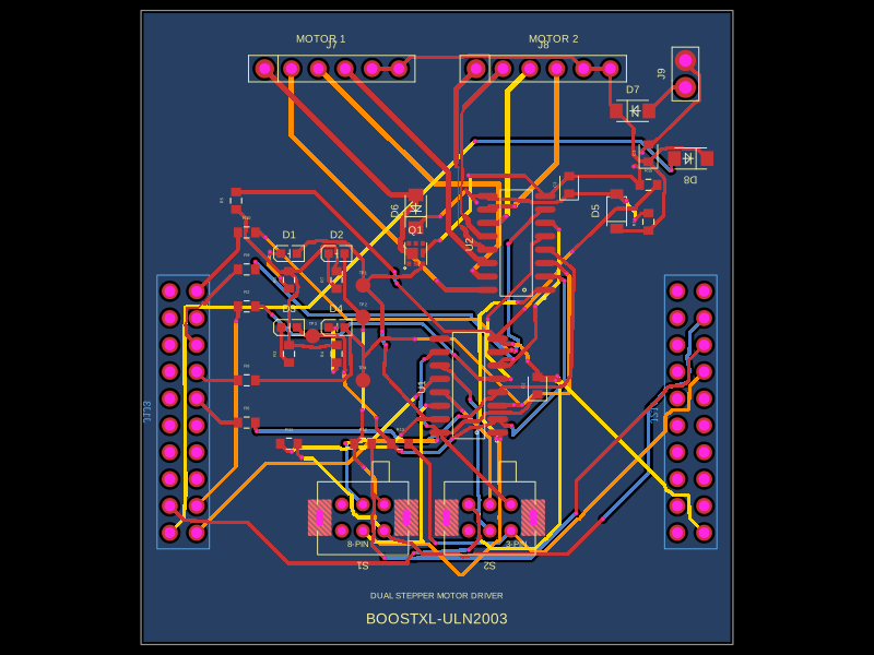 More from this authorabse/boostxl-uln2003This code defines a React component that models a through-hole or surface-mount LED with specified pin labels, footprint, silkscreen, and 3D CAD model for PCB layout.
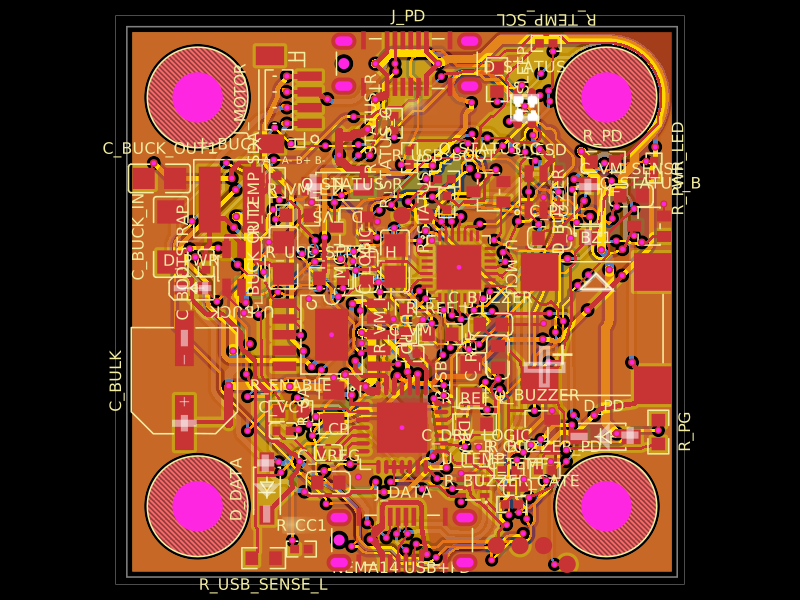 Discover something newAnasSarkiz/NEMA14_CH32X035G8U6A NEMA stepper motor is shown with proposed M3 screws/spacers, four wired motor leads and splices, and a JST SHR-04V-S connector.