abse/gameboy-advance
A tscircuit package created by abse.
- Version
- 0.0.45
- License
- unset
- Stars
- 0
firmware/game-console/sd-fatfs/sd_driver/SDIO/rp2040_sdio.c
// Implementation of SDIO communication for RP2040
//
// The RP2040 official work-in-progress code at
// https://github.com/raspberrypi/pico-extras/tree/master/src/rp2_common/pico_sd_card
// may be useful reference, but this is independent implementation.
//
// For official SDIO specifications, refer to:
// https://www.sdcard.org/downloads/pls/
// "SDIO Physical Layer Simplified Specification Version 8.00"

#include <assert.h>
#include <string.h>
#include <stdlib.h>
//
#include "hardware/dma.h"
#include "hardware/gpio.h"
#include "hardware/pio.h"
#if !PICO_RISCV
#  if PICO_RP2040
#    include "RP2040.h"
#  endif
#  if PICO_RP2350
#    include "RP2350.h"
#  endif
#endif
//
#include "dma_interrupts.h"
#include "hw_config.h"
#include "rp2040_sdio.h"
#include "rp2040_sdio.pio.h"
#include "delays.h"
#include "sd_card.h"
#include "sd_timeouts.h"
#include "my_debug.h"
#include "util.h"
//
#include "rp2040_sdio.h"

#define azdbg(arg1, ...) {\
    DBG_PRINTF("%s,%s:%d %s\n", __func__, __FILE__, __LINE__, arg1); \
}

#define STATE sd_card_p->sdio_if_p->state
#define SDIO_PIO sd_card_p->sdio_if_p->SDIO_PIO
#define SDIO_CMD_SM STATE.SDIO_CMD_SM
#define SDIO_DATA_SM STATE.SDIO_DATA_SM
#define SDIO_DMA_CH STATE.SDIO_DMA_CH
#define SDIO_DMA_CHB STATE.SDIO_DMA_CHB

#define SDIO_CMD sd_card_p->sdio_if_p->CMD_gpio
#define SDIO_CLK sd_card_p->sdio_if_p->CLK_gpio
#define SDIO_D0 sd_card_p->sdio_if_p->D0_gpio
#define SDIO_D1 sd_card_p->sdio_if_p->D1_gpio
#define SDIO_D2 sd_card_p->sdio_if_p->D2_gpio
#define SDIO_D3 sd_card_p->sdio_if_p->D3_gpio


// Force everything to idle state
static sdio_status_t rp2040_sdio_stop(sd_card_t *sd_card_p);

/*******************************************************
 * Checksum algorithms
 *******************************************************/

// Table lookup for calculating CRC-7 checksum that is used in SDIO command packets.
// Usage:
//    uint8_t crc = 0;
//    crc = crc7_table[crc ^ byte];
//    .. repeat for every byte ..
static const uint8_t crc7_table[256] = {
	0x00, 0x12, 0x24, 0x36, 0x48, 0x5a, 0x6c, 0x7e,	0x90, 0x82, 0xb4, 0xa6, 0xd8, 0xca, 0xfc, 0xee,
	0x32, 0x20, 0x16, 0x04, 0x7a, 0x68, 0x5e, 0x4c,	0xa2, 0xb0, 0x86, 0x94, 0xea, 0xf8, 0xce, 0xdc,
	0x64, 0x76, 0x40, 0x52, 0x2c, 0x3e, 0x08, 0x1a,	0xf4, 0xe6, 0xd0, 0xc2, 0xbc, 0xae, 0x98, 0x8a,
	0x56, 0x44, 0x72, 0x60, 0x1e, 0x0c, 0x3a, 0x28,	0xc6, 0xd4, 0xe2, 0xf0, 0x8e, 0x9c, 0xaa, 0xb8,
	0xc8, 0xda, 0xec, 0xfe, 0x80, 0x92, 0xa4, 0xb6,	0x58, 0x4a, 0x7c, 0x6e, 0x10, 0x02, 0x34, 0x26,
	0xfa, 0xe8, 0xde, 0xcc, 0xb2, 0xa0, 0x96, 0x84,	0x6a, 0x78, 0x4e, 0x5c, 0x22, 0x30, 0x06, 0x14,
	0xac, 0xbe, 0x88, 0x9a, 0xe4, 0xf6, 0xc0, 0xd2,	0x3c, 0x2e, 0x18, 0x0a, 0x74, 0x66, 0x50, 0x42,
	0x9e, 0x8c, 0xba, 0xa8, 0xd6, 0xc4, 0xf2, 0xe0,	0x0e, 0x1c, 0x2a, 0x38, 0x46, 0x54, 0x62, 0x70,
	0x82, 0x90, 0xa6, 0xb4, 0xca, 0xd8, 0xee, 0xfc,	0x12, 0x00, 0x36, 0x24, 0x5a, 0x48, 0x7e, 0x6c,
	0xb0, 0xa2, 0x94, 0x86, 0xf8, 0xea, 0xdc, 0xce,	0x20, 0x32, 0x04, 0x16, 0x68, 0x7a, 0x4c, 0x5e,
	0xe6, 0xf4, 0xc2, 0xd0, 0xae, 0xbc, 0x8a, 0x98,	0x76, 0x64, 0x52, 0x40, 0x3e, 0x2c, 0x1a, 0x08,
	0xd4, 0xc6, 0xf0, 0xe2, 0x9c, 0x8e, 0xb8, 0xaa,	0x44, 0x56, 0x60, 0x72, 0x0c, 0x1e, 0x28, 0x3a,
	0x4a, 0x58, 0x6e, 0x7c, 0x02, 0x10, 0x26, 0x34,	0xda, 0xc8, 0xfe, 0xec, 0x92, 0x80, 0xb6, 0xa4,
	0x78, 0x6a, 0x5c, 0x4e, 0x30, 0x22, 0x14, 0x06,	0xe8, 0xfa, 0xcc, 0xde, 0xa0, 0xb2, 0x84, 0x96,
	0x2e, 0x3c, 0x0a, 0x18, 0x66, 0x74, 0x42, 0x50,	0xbe, 0xac, 0x9a, 0x88, 0xf6, 0xe4, 0xd2, 0xc0,
	0x1c, 0x0e, 0x38, 0x2a, 0x54, 0x46, 0x70, 0x62,	0x8c, 0x9e, 0xa8, 0xba, 0xc4, 0xd6, 0xe0, 0xf2
};

// Calculate the CRC16 checksum for parallel 4 bit lines separately.
// When the SDIO bus operates in 4-bit mode, the CRC16 algorithm
// is applied to each line separately and generates total of
// 4 x 16 = 64 bits of checksum.
__attribute__((optimize("Ofast")))
uint64_t sdio_crc16_4bit_checksum(uint32_t *data, uint32_t num_words)
{
    uint64_t crc = 0;
    uint32_t *end = data + num_words;
    while (data < end)
    {
        for (int unroll = 0; unroll < 4; unroll++)
        {
            // Each 32-bit word contains 8 bits per line.
            // Reverse the bytes because SDIO protocol is big-endian.
            uint32_t data_in = __builtin_bswap32(*data++);

            // Shift out 8 bits for each line
            uint32_t data_out = crc >> 32;
            crc <<= 32;

            // XOR outgoing data to itself with 4 bit delay
            data_out ^= (data_out >> 16);

            // XOR incoming data to outgoing data with 4 bit delay
            data_out ^= (data_in >> 16);

            // XOR outgoing and incoming data to accumulator at each tap
            uint64_t xorred = data_out ^ data_in;
            crc ^= xorred;
            crc ^= xorred << (5 * 4);
            crc ^= xorred << (12 * 4);
        }
    }

    return crc;
}

/*******************************************************
 * Basic SDIO command execution
 *******************************************************/

static void sdio_send_command(const sd_card_t *sd_card_p, uint8_t command, uint32_t arg, uint8_t response_bits)
{
    // azdbg("SDIO Command: ", (int)command, " arg ", arg);

    // Format the arguments in the way expected by the PIO code.
    uint32_t word0 =
        (47 << 24) | // Number of bits in command minus one
        ( 1 << 22) | // Transfer direction from host to card
        (command << 16) | // Command byte
        (((arg >> 24) & 0xFF) << 8) | // MSB byte of argument
        (((arg >> 16) & 0xFF) << 0);

    uint32_t word1 =
        (((arg >> 8) & 0xFF) << 24) |
        (((arg >> 0) & 0xFF) << 16) | // LSB byte of argument
        ( 1 << 8); // End bit

    // Set number of bits in response minus one, or leave at 0 if no response expected
    if (response_bits)
    {
        word1 |= ((response_bits - 1) << 0);
    }

    // Calculate checksum in the order that the bytes will be transmitted (big-endian)
    uint8_t crc = 0;
    crc = crc7_table[crc ^ ((word0 >> 16) & 0xFF)];
    crc = crc7_table[crc ^ ((word0 >>  8) & 0xFF)];
    crc = crc7_table[crc ^ ((word0 >>  0) & 0xFF)];
    crc = crc7_table[crc ^ ((word1 >> 24) & 0xFF)];
    crc = crc7_table[crc ^ ((word1 >> 16) & 0xFF)];
    word1 |= crc << 8;

    // Transmit command
    pio_sm_clear_fifos(SDIO_PIO, SDIO_CMD_SM);
    pio_sm_put(SDIO_PIO, SDIO_CMD_SM, word0);
    pio_sm_put(SDIO_PIO, SDIO_CMD_SM, word1);
}

sdio_status_t rp2040_sdio_command_R1(sd_card_t *sd_card_p, uint8_t command, uint32_t arg, uint32_t *response)
{
    sdio_send_command(sd_card_p, command, arg, response ? 48 : 0);

    // Wait for response
    uint32_t start = millis();
    uint32_t wait_words = response ? 2 : 1;
    while (pio_sm_get_rx_fifo_level(SDIO_PIO, SDIO_CMD_SM) < wait_words)
    {
        if ((uint32_t)(millis() - start) > sd_timeouts.rp2040_sdio_command_R1)
        {
            if (command != 8) // Don't log for missing SD card
            {
                azdbg("Timeout waiting for response in rp2040_sdio_command_R1(", (int)command, "), ",
                    "PIO PC: ", (int)pio_sm_get_pc(SDIO_PIO, SDIO_CMD_SM) - (int)STATE.pio_cmd_clk_offset,
                    " RXF: ", (int)pio_sm_get_rx_fifo_level(SDIO_PIO, SDIO_CMD_SM),
                    " TXF: ", (int)pio_sm_get_tx_fifo_level(SDIO_PIO, SDIO_CMD_SM));
                EMSG_PRINTF("%s: Timeout waiting for response in rp2040_sdio_command_R1(0x%hx)\n", __func__, command);
            }

            // Reset the state machine program
            pio_sm_clear_fifos(SDIO_PIO, SDIO_CMD_SM);
            pio_sm_exec(SDIO_PIO, SDIO_CMD_SM, pio_encode_jmp(STATE.pio_cmd_clk_offset));
            return SDIO_ERR_RESPONSE_TIMEOUT;
        }
    }

    if (response)
    {
        // Read out response packet
        uint32_t resp0 = pio_sm_get(SDIO_PIO, SDIO_CMD_SM);
        uint32_t resp1 = pio_sm_get(SDIO_PIO, SDIO_CMD_SM);
        // azdbg("SDIO R1 response: ", resp0, " ", resp1);

        // Calculate response checksum
        uint8_t crc = 0;
        crc = crc7_table[crc ^ ((resp0 >> 24) & 0xFF)];
        crc = crc7_table[crc ^ ((resp0 >> 16) & 0xFF)];
        crc = crc7_table[crc ^ ((resp0 >>  8) & 0xFF)];
        crc = crc7_table[crc ^ ((resp0 >>  0) & 0xFF)];
        crc = crc7_table[crc ^ ((resp1 >>  8) & 0xFF)];

        uint8_t actual_crc = ((resp1 >> 0) & 0xFE);
        if (crc != actual_crc)
        {
            // azdbg("rp2040_sdio_command_R1(", (int)command, "): CRC error, calculated ", crc, " packet has ", actual_crc);
            EMSG_PRINTF("rp2040_sdio_command_R1(%d): CRC error, calculated 0x%hx, packet has 0x%hx\n", command, crc, actual_crc);
            return SDIO_ERR_RESPONSE_CRC;
        }

        uint8_t response_cmd = ((resp0 >> 24) & 0xFF);
        if (response_cmd != command && command != 41)
        {
            // azdbg("rp2040_sdio_command_R1(", (int)command, "): received reply for ", (int)response_cmd);
            EMSG_PRINTF("%d rp2040_sdio_command_R1(%d): received reply for %d\n", __LINE__, command, response_cmd);
            return SDIO_ERR_RESPONSE_CODE;
        }

        *response = ((resp0 & 0xFFFFFF) << 8) | ((resp1 >> 8) & 0xFF);
    }
    else
    {
        // Read out dummy marker
        pio_sm_get(SDIO_PIO, SDIO_CMD_SM);
    }

    return SDIO_OK;
}

sdio_status_t rp2040_sdio_command_R2(const sd_card_t *sd_card_p, uint8_t command, uint32_t arg, uint8_t *response)
{
    // The response is too long to fit in the PIO FIFO, so use DMA to receive it.
    pio_sm_clear_fifos(SDIO_PIO, SDIO_CMD_SM);
    uint32_t response_buf[5];
    dma_channel_config dmacfg = dma_channel_get_default_config(SDIO_DMA_CH);
    channel_config_set_transfer_data_size(&dmacfg, DMA_SIZE_32);
    channel_config_set_read_increment(&dmacfg, false);
    channel_config_set_write_increment(&dmacfg, true);
    channel_config_set_dreq(&dmacfg, pio_get_dreq(SDIO_PIO, SDIO_CMD_SM, false));
    dma_channel_configure(SDIO_DMA_CH, &dmacfg, &response_buf, &SDIO_PIO->rxf[SDIO_CMD_SM], 5, true);

    sdio_send_command(sd_card_p, command, arg, 136);

    uint32_t start = millis();
    while (dma_channel_is_busy(SDIO_DMA_CH))
    {
        if ((uint32_t)(millis() - start) > sd_timeouts.rp2040_sdio_command_R2)
        {
            azdbg("Timeout waiting for response in rp2040_sdio_command_R2(", (int)command, "), ",
                  "PIO PC: ", (int)pio_sm_get_pc(SDIO_PIO, SDIO_CMD_SM) - (int)STATE.pio_cmd_clk_offset,
                  " RXF: ", (int)pio_sm_get_rx_fifo_level(SDIO_PIO, SDIO_CMD_SM),
                  " TXF: ", (int)pio_sm_get_tx_fifo_level(SDIO_PIO, SDIO_CMD_SM));

            // Reset the state machine program
            dma_channel_abort(SDIO_DMA_CH);
            pio_sm_clear_fifos(SDIO_PIO, SDIO_CMD_SM);
            pio_sm_exec(SDIO_PIO, SDIO_CMD_SM, pio_encode_jmp(STATE.pio_cmd_clk_offset));
            return SDIO_ERR_RESPONSE_TIMEOUT;
        }
    }

    dma_channel_abort(SDIO_DMA_CH);

    // Copy the response payload to output buffer
    response[0]  = ((response_buf[0] >> 16) & 0xFF);
    response[1]  = ((response_buf[0] >>  8) & 0xFF);
    response[2]  = ((response_buf[0] >>  0) & 0xFF);
    response[3]  = ((response_buf[1] >> 24) & 0xFF);
    response[4]  = ((response_buf[1] >> 16) & 0xFF);
    response[5]  = ((response_buf[1] >>  8) & 0xFF);
    response[6]  = ((response_buf[1] >>  0) & 0xFF);
    response[7]  = ((response_buf[2] >> 24) & 0xFF);
    response[8]  = ((response_buf[2] >> 16) & 0xFF);
    response[9]  = ((response_buf[2] >>  8) & 0xFF);
    response[10] = ((response_buf[2] >>  0) & 0xFF);
    response[11] = ((response_buf[3] >> 24) & 0xFF);
    response[12] = ((response_buf[3] >> 16) & 0xFF);
    response[13] = ((response_buf[3] >>  8) & 0xFF);
    response[14] = ((response_buf[3] >>  0) & 0xFF);
    response[15] = ((response_buf[4] >>  0) & 0xFF);

    // Calculate checksum of the payload
    uint8_t crc = 0;
    for (int i = 0; i < 15; i++)
    {
        crc = crc7_table[crc ^ response[i]];
    }

    uint8_t actual_crc = response[15] & 0xFE;
    if (crc != actual_crc)
    {
        azdbg("rp2040_sdio_command_R2(", (int)command, "): CRC error, calculated ", crc, " packet has ", actual_crc);
        return SDIO_ERR_RESPONSE_CRC;
    }

    uint8_t response_cmd = ((response_buf[0] >> 24) & 0xFF);
    if (response_cmd != 0x3F)
    {
        azdbg("rp2040_sdio_command_R2(", (int)command, "): Expected reply code 0x3F");
        return SDIO_ERR_RESPONSE_CODE;
    }

    return SDIO_OK;
}

sdio_status_t rp2040_sdio_command_R3(sd_card_t *sd_card_p, uint8_t command, uint32_t arg, uint32_t *response)
{
    sdio_send_command(sd_card_p, command, arg, 48);

    // Wait for response
    uint32_t start = millis();
    while (pio_sm_get_rx_fifo_level(SDIO_PIO, SDIO_CMD_SM) < 2)
    {
        if ((uint32_t)(millis() - start) > sd_timeouts.rp2040_sdio_command_R3)
        {
            azdbg("Timeout waiting for response in rp2040_sdio_command_R3(", (int)command, "), ",
                  "PIO PC: ", (int)pio_sm_get_pc(SDIO_PIO, SDIO_CMD_SM) - (int)STATE.pio_cmd_clk_offset,
                  " RXF: ", (int)pio_sm_get_rx_fifo_level(SDIO_PIO, SDIO_CMD_SM),
                  " TXF: ", (int)pio_sm_get_tx_fifo_level(SDIO_PIO, SDIO_CMD_SM));

            // Reset the state machine program
            pio_sm_clear_fifos(SDIO_PIO, SDIO_CMD_SM);
            pio_sm_exec(SDIO_PIO, SDIO_CMD_SM, pio_encode_jmp(STATE.pio_cmd_clk_offset));
            return SDIO_ERR_RESPONSE_TIMEOUT;
        }
    }

    // Read out response packet
    uint32_t resp0 = pio_sm_get(SDIO_PIO, SDIO_CMD_SM);
    uint32_t resp1 = pio_sm_get(SDIO_PIO, SDIO_CMD_SM);
    *response = ((resp0 & 0xFFFFFF) << 8) | ((resp1 >> 8) & 0xFF);
    // azdbg("SDIO R3 response: ", resp0, " ", resp1);

    return SDIO_OK;
}

/*******************************************************
 * Data reception from SD card
 *******************************************************/

sdio_status_t rp2040_sdio_rx_start(sd_card_t *sd_card_p, uint8_t *buffer, uint32_t num_blocks, size_t block_size)
{
    // Buffer must be aligned
    assert(((uint32_t)buffer & 3) == 0 && num_blocks <= SDIO_MAX_BLOCKS);

    STATE.transfer_state = SDIO_RX;
    STATE.transfer_start_time = millis();
    STATE.data_buf = (uint32_t*)buffer;
    STATE.blocks_done = 0;
    STATE.total_blocks = num_blocks;
    STATE.blocks_checksumed = 0;
    STATE.checksum_errors = 0;

    // Create DMA block descriptors to store each block of 512 bytes of data to buffer
    // and then 8 bytes to STATE.received_checksums.
    for (uint32_t i = 0; i < num_blocks; i++)
    {
        STATE.dma_blocks[i * 2].write_addr = buffer + i * block_size;
        STATE.dma_blocks[i * 2].transfer_count = block_size / sizeof(uint32_t);

        STATE.dma_blocks[i * 2 + 1].write_addr = &STATE.received_checksums[i];
        STATE.dma_blocks[i * 2 + 1].transfer_count = 2;
    }
    STATE.dma_blocks[num_blocks * 2].write_addr = 0;
    STATE.dma_blocks[num_blocks * 2].transfer_count = 0;

    // Configure first DMA channel for reading from the PIO RX fifo
    dma_channel_config dmacfg = dma_channel_get_default_config(SDIO_DMA_CH);
    channel_config_set_transfer_data_size(&dmacfg, DMA_SIZE_32);
    channel_config_set_read_increment(&dmacfg, false);
    channel_config_set_write_increment(&dmacfg, true);
    channel_config_set_dreq(&dmacfg, pio_get_dreq(SDIO_PIO, SDIO_DATA_SM, false));
    channel_config_set_bswap(&dmacfg, true);
    channel_config_set_chain_to(&dmacfg, SDIO_DMA_CHB);
    dma_channel_configure(SDIO_DMA_CH, &dmacfg, 0, &SDIO_PIO->rxf[SDIO_DATA_SM], 0, false);

    // Configure second DMA channel for reconfiguring the first one
    dmacfg = dma_channel_get_default_config(SDIO_DMA_CHB);
    channel_config_set_transfer_data_size(&dmacfg, DMA_SIZE_32);
    channel_config_set_read_increment(&dmacfg, true);
    channel_config_set_write_increment(&dmacfg, true);
    channel_config_set_ring(&dmacfg, true, 3);
    dma_channel_configure(SDIO_DMA_CHB, &dmacfg, &dma_hw->ch[SDIO_DMA_CH].al1_write_addr,
        STATE.dma_blocks, 2, false);

    // Initialize PIO state machine
    pio_sm_init(SDIO_PIO, SDIO_DATA_SM, STATE.pio_data_rx_offset, &STATE.pio_cfg_data_rx);
    pio_sm_set_consecutive_pindirs(SDIO_PIO, SDIO_DATA_SM, SDIO_D0, 4, false);

    // Write number of nibbles to receive to Y register
    pio_sm_put(SDIO_PIO, SDIO_DATA_SM, block_size * 2 + 16 - 1);
    pio_sm_exec(SDIO_PIO, SDIO_DATA_SM, pio_encode_out(pio_y, 32));

    // Enable RX FIFO join because we don't need the TX FIFO during transfer.
    // This gives more leeway for the DMA block switching
    SDIO_PIO->sm[SDIO_DATA_SM].shiftctrl |= PIO_SM0_SHIFTCTRL_FJOIN_RX_BITS;

    // Start PIO and DMA
    dma_channel_start(SDIO_DMA_CHB);
    pio_sm_set_enabled(SDIO_PIO, SDIO_DATA_SM, true);

    return SDIO_OK;
}

// Check checksums for received blocks
static void sdio_verify_rx_checksums(sd_card_t *sd_card_p, uint32_t maxcount, size_t block_size_words)
{
    while (STATE.blocks_checksumed < STATE.blocks_done && maxcount-- > 0)
    {
        // Calculate checksum from received data
        int blockidx = STATE.blocks_checksumed++;
        uint64_t checksum = sdio_crc16_4bit_checksum(STATE.data_buf + blockidx * block_size_words,
                                                     block_size_words);

        // Convert received checksum to little-endian format
        uint32_t top = __builtin_bswap32(STATE.received_checksums[blockidx].top);
        uint32_t bottom = __builtin_bswap32(STATE.received_checksums[blockidx].bottom);
        uint64_t expected = ((uint64_t)top << 32) | bottom;

        if (checksum != expected)
        {
            STATE.checksum_errors++;
            if (STATE.checksum_errors == 1)
            {
                EMSG_PRINTF("SDIO checksum error in reception: block %d calculated 0x%llx expected 0x%llx\n",
                    blockidx, checksum, expected);
                dump_bytes(block_size_words, (uint8_t *)STATE.data_buf + blockidx * block_size_words);
            }
        }
    }
}

sdio_status_t rp2040_sdio_rx_poll(sd_card_t *sd_card_p, size_t block_size_words)
{
    // Was everything done when the previous rx_poll() finished?
    if (STATE.blocks_done >= STATE.total_blocks)
    {
        STATE.transfer_state = SDIO_IDLE;
    }
    else
    {
        // Use the idle time to calculate checksums
        sdio_verify_rx_checksums(sd_card_p, 4, block_size_words);

        // Check how many DMA control blocks have been consumed
        uint32_t dma_ctrl_block_count = (dma_hw->ch[SDIO_DMA_CHB].read_addr - (uint32_t)&STATE.dma_blocks);
        dma_ctrl_block_count /= sizeof(STATE.dma_blocks[0]);

        // Compute how many complete SDIO blocks have been transferred
        // When transfer ends, dma_ctrl_block_count == STATE.total_blocks * 2 + 1
        STATE.blocks_done = (dma_ctrl_block_count - 1) / 2;

        // NOTE: When all blocks are done, rx_poll() still returns SDIO_BUSY once.
        // This provides a chance to start the SCSI transfer before the last checksums
        // are computed. Any checksum failures can be indicated in SCSI status after
        // the data transfer has finished.
    }

    if (STATE.transfer_state == SDIO_IDLE)
    {
        // Verify all remaining checksums.
        sdio_verify_rx_checksums(sd_card_p, STATE.total_blocks, block_size_words);

        if (STATE.checksum_errors == 0)
            return SDIO_OK;
        else
            return SDIO_ERR_DATA_CRC;
    }
    else if (millis() - STATE.transfer_start_time >= sd_timeouts.rp2040_sdio_rx_poll)
    {
        azdbg("rp2040_sdio_rx_poll() timeout, "
            "PIO PC: ", (int)pio_sm_get_pc(SDIO_PIO, SDIO_DATA_SM) - (int)STATE.pio_data_rx_offset,
            " RXF: ", (int)pio_sm_get_rx_fifo_level(SDIO_PIO, SDIO_DATA_SM),
            " TXF: ", (int)pio_sm_get_tx_fifo_level(SDIO_PIO, SDIO_DATA_SM),
            " DMA CNT: ", dma_hw->ch[SDIO_DMA_CH].al2_transfer_count);
        rp2040_sdio_stop(sd_card_p);
        return SDIO_ERR_DATA_TIMEOUT;
    }

    return SDIO_BUSY;
}


/*******************************************************
 * Data transmission to SD card
 *******************************************************/

static void sdio_start_next_block_tx(sd_card_t *sd_card_p)
{
    // Initialize PIO
    pio_sm_init(SDIO_PIO, SDIO_DATA_SM, STATE.pio_data_tx_offset, &STATE.pio_cfg_data_tx);

    // Configure DMA to send the data block payload (512 bytes)
    dma_channel_config dmacfg = dma_channel_get_default_config(SDIO_DMA_CH);
    channel_config_set_transfer_data_size(&dmacfg, DMA_SIZE_32);
    channel_config_set_read_increment(&dmacfg, true);
    channel_config_set_write_increment(&dmacfg, false);
    channel_config_set_dreq(&dmacfg, pio_get_dreq(SDIO_PIO, SDIO_DATA_SM, true));
    channel_config_set_bswap(&dmacfg, true);
    channel_config_set_chain_to(&dmacfg, SDIO_DMA_CHB);
    dma_channel_configure(SDIO_DMA_CH, &dmacfg,
        &SDIO_PIO->txf[SDIO_DATA_SM], STATE.data_buf + STATE.blocks_done * SDIO_WORDS_PER_BLOCK,
        SDIO_WORDS_PER_BLOCK, false);

    // Prepare second DMA channel to send the CRC and block end marker
    uint64_t crc = STATE.next_wr_block_checksum;
    STATE.end_token_buf[0] = (uint32_t)(crc >> 32);
    STATE.end_token_buf[1] = (uint32_t)(crc >>  0);
    STATE.end_token_buf[2] = 0xFFFFFFFF;
    channel_config_set_bswap(&dmacfg, false);
    dma_channel_configure(SDIO_DMA_CHB, &dmacfg,
        &SDIO_PIO->txf[SDIO_DATA_SM], STATE.end_token_buf, 3, false);

    // Enable IRQ to trigger when block is done
    switch (sd_card_p->sdio_if_p->DMA_IRQ_num) {
        case DMA_IRQ_0:
            // Clear any pending interrupt service request:
            dma_hw->ints0 = 1 << SDIO_DMA_CHB;
            dma_channel_set_irq0_enabled(SDIO_DMA_CHB, true);
            break;
        case DMA_IRQ_1:
            // Clear any pending interrupt service request:
            dma_hw->ints1 = 1 << SDIO_DMA_CHB;
            dma_channel_set_irq1_enabled(SDIO_DMA_CHB, true);
            break;
        default:
            assert(false);
    }

    // Initialize register X with nibble count and register Y with response bit count
    pio_sm_put(SDIO_PIO, SDIO_DATA_SM, 1048);
    pio_sm_exec(SDIO_PIO, SDIO_DATA_SM, pio_encode_out(pio_x, 32));
    pio_sm_put(SDIO_PIO, SDIO_DATA_SM, 31);
    pio_sm_exec(SDIO_PIO, SDIO_DATA_SM, pio_encode_out(pio_y, 32));

    // Initialize pins to output and high
    pio_sm_exec(SDIO_PIO, SDIO_DATA_SM, pio_encode_set(pio_pins, 15));
    pio_sm_exec(SDIO_PIO, SDIO_DATA_SM, pio_encode_set(pio_pindirs, 15));

    // Write start token and start the DMA transfer.
    pio_sm_put(SDIO_PIO, SDIO_DATA_SM, 0xFFFFFFF0);
    dma_channel_start(SDIO_DMA_CH);

    // Start state machine
    pio_sm_set_enabled(SDIO_PIO, SDIO_DATA_SM, true);
}

static void sdio_compute_next_tx_checksum(sd_card_t *sd_card_p)
{
    assert (STATE.blocks_done < STATE.total_blocks && STATE.blocks_checksumed < STATE.total_blocks);
    int blockidx = STATE.blocks_checksumed++;
    STATE.next_wr_block_checksum = sdio_crc16_4bit_checksum(STATE.data_buf + blockidx * SDIO_WORDS_PER_BLOCK,
                                                             SDIO_WORDS_PER_BLOCK);
}

// Start transferring data from memory to SD card
sdio_status_t rp2040_sdio_tx_start(sd_card_t *sd_card_p, const uint8_t *buffer, uint32_t num_blocks)
{
    // Buffer must be aligned
    assert(((uint32_t)buffer & 3) == 0 && num_blocks <= SDIO_MAX_BLOCKS);

    STATE.transfer_state = SDIO_TX;
    STATE.transfer_start_time = millis();
    STATE.data_buf = (uint32_t*)buffer;
    STATE.blocks_done = 0;
    STATE.total_blocks = num_blocks;
    STATE.blocks_checksumed = 0;
    STATE.checksum_errors = 0;

    // Compute first block checksum
    sdio_compute_next_tx_checksum(sd_card_p);

    // Start first DMA transfer and PIO
    sdio_start_next_block_tx(sd_card_p);

    if (STATE.blocks_checksumed < STATE.total_blocks)
    {
        // Precompute second block checksum
        sdio_compute_next_tx_checksum(sd_card_p);
    }

    return SDIO_OK;
}

static sdio_status_t check_sdio_write_response(uint32_t card_response)
{
    // Shift card response until top bit is 0 (the start bit)
    // The format of response is poorly documented in SDIO spec but refer to e.g.
    // http://my-cool-projects.blogspot.com/2013/02/the-mysterious-sd-card-crc-status.html
    uint32_t resp = card_response;
    if (!(~resp & 0xFFFF0000)) resp <<= 16;
    if (!(~resp & 0xFF000000)) resp <<= 8;
    if (!(~resp & 0xF0000000)) resp <<= 4;
    if (!(~resp & 0xC0000000)) resp <<= 2;
    if (!(~resp & 0x80000000)) resp <<= 1;

    uint32_t wr_status = (resp >> 28) & 7;

    if (wr_status == 2)
    {
        return SDIO_OK;
    }
    else if (wr_status == 5)
    {
        EMSG_PRINTF("SDIO card reports write CRC error, status %lx\n", card_response);
        return SDIO_ERR_WRITE_CRC;
    }
    else if (wr_status == 6)
    {
        EMSG_PRINTF("SDIO card reports write failure, status %lx\n", card_response);
        return SDIO_ERR_WRITE_FAIL;
    }
    else
    {
        EMSG_PRINTF("SDIO card reports unknown write status %lx\n", card_response);
        return SDIO_ERR_WRITE_FAIL;
    }
}

// When a block finishes, this IRQ handler starts the next one
void sdio_irq_handler(sd_card_t *sd_card_p) {
    if (STATE.transfer_state == SDIO_TX)
    {
        if (!dma_channel_is_busy(SDIO_DMA_CH) && !dma_channel_is_busy(SDIO_DMA_CHB))
        {
            // Main data transfer is finished now.
            // When card is ready, PIO will put card response on RX fifo
            STATE.transfer_state = SDIO_TX_WAIT_IDLE;
            if (!pio_sm_is_rx_fifo_empty(SDIO_PIO, SDIO_DATA_SM))
            {
                // Card is already idle
                STATE.card_response = pio_sm_get(SDIO_PIO, SDIO_DATA_SM);
            }
            else
            {
                // Use DMA to wait for the response
                dma_channel_config dmacfg = dma_channel_get_default_config(SDIO_DMA_CHB);
                channel_config_set_transfer_data_size(&dmacfg, DMA_SIZE_32);
                channel_config_set_read_increment(&dmacfg, false);
                channel_config_set_write_increment(&dmacfg, false);
                channel_config_set_dreq(&dmacfg, pio_get_dreq(SDIO_PIO, SDIO_DATA_SM, false));
                dma_channel_configure(SDIO_DMA_CHB, &dmacfg,
                    &STATE.card_response, &SDIO_PIO->rxf[SDIO_DATA_SM], 1, true);
            }
        }
    }

    if (STATE.transfer_state == SDIO_TX_WAIT_IDLE)
    {
        if (!dma_channel_is_busy(SDIO_DMA_CHB))
        {
            STATE.wr_status = check_sdio_write_response(STATE.card_response);

            if (STATE.wr_status != SDIO_OK)
            {
                rp2040_sdio_stop(sd_card_p);
                return;
            }

            STATE.blocks_done++;
            if (STATE.blocks_done < STATE.total_blocks)
            {
                sdio_start_next_block_tx(sd_card_p);
                STATE.transfer_state = SDIO_TX;

                if (STATE.blocks_checksumed < STATE.total_blocks)
                {
                    // Precompute the CRC for next block so that it is ready when
                    // we want to send it.
                    sdio_compute_next_tx_checksum(sd_card_p);
                }
            }
            else
            {
                rp2040_sdio_stop(sd_card_p);
            }
        }
    }
}

// Check if transmission is complete
sdio_status_t rp2040_sdio_tx_poll(sd_card_t *sd_card_p, uint32_t *bytes_complete)
{
#if !PICO_RISCV
    if (SCB->ICSR & SCB_ICSR_VECTACTIVE_Msk)
    {
        // Verify that IRQ handler gets called even if we are in hardfault handler
        sdio_irq_handler(sd_card_p);
    }
#endif

    if (bytes_complete)
    {
        *bytes_complete = STATE.blocks_done * SDIO_BLOCK_SIZE;
    }

    if (STATE.transfer_state == SDIO_IDLE)
    {
        rp2040_sdio_stop(sd_card_p);
        return STATE.wr_status;
    }
    else if (millis() - STATE.transfer_start_time >= sd_timeouts.rp2040_sdio_tx_poll)
    {
        EMSG_PRINTF("rp2040_sdio_tx_poll() timeout\n");
        DBG_PRINTF("rp2040_sdio_tx_poll() timeout, "
            "PIO PC: %d"
            " RXF: %d"
            " TXF: %d"
            " DMA CNT: %lu\n",
            (int)pio_sm_get_pc(SDIO_PIO, SDIO_DATA_SM) - (int)STATE.pio_data_tx_offset,
            (int)pio_sm_get_rx_fifo_level(SDIO_PIO, SDIO_DATA_SM),
            (int)pio_sm_get_tx_fifo_level(SDIO_PIO, SDIO_DATA_SM),
            dma_hw->ch[SDIO_DMA_CH].al2_transfer_count
        );
        rp2040_sdio_stop(sd_card_p);
        return SDIO_ERR_DATA_TIMEOUT;
    }

    return SDIO_BUSY;
}

// Force everything to idle state
static sdio_status_t rp2040_sdio_stop(sd_card_t *sd_card_p)
{
    dma_channel_abort(SDIO_DMA_CH);
    dma_channel_abort(SDIO_DMA_CHB);
    switch (sd_card_p->sdio_if_p->DMA_IRQ_num) {
    case DMA_IRQ_0:
            dma_channel_set_irq0_enabled(SDIO_DMA_CHB, false);
        break;
    case DMA_IRQ_1:
            dma_channel_set_irq1_enabled(SDIO_DMA_CHB, false);
        break;
    default:
        myASSERT(false);
    }

    pio_sm_set_enabled(SDIO_PIO, SDIO_DATA_SM, false);
    pio_sm_set_consecutive_pindirs(SDIO_PIO, SDIO_DATA_SM, SDIO_D0, 4, false);
    STATE.transfer_state = SDIO_IDLE;
    return SDIO_OK;
}

bool rp2040_sdio_init(sd_card_t *sd_card_p, float clk_div) {
    // Mark resources as being in use, unless it has been done already.
    if (!STATE.resources_claimed) {

        if (!SDIO_PIO)
            SDIO_PIO = pio0; // Default
        if (!sd_card_p->sdio_if_p->DMA_IRQ_num)
            sd_card_p->sdio_if_p->DMA_IRQ_num = DMA_IRQ_0; // Default

        // pio_sm_claim(SDIO_PIO, SDIO_CMD_SM);
        // int pio_claim_unused_sm(PIO pio, bool required);
        SDIO_CMD_SM = pio_claim_unused_sm(SDIO_PIO, true);
        // pio_sm_claim(SDIO_PIO, SDIO_DATA_SM);
        SDIO_DATA_SM = pio_claim_unused_sm(SDIO_PIO, true);
        // dma_channel_claim(SDIO_DMA_CH);
        SDIO_DMA_CH = dma_claim_unused_channel(true);
        // dma_channel_claim(SDIO_DMA_CHB);
        SDIO_DMA_CHB = dma_claim_unused_channel(true);

        /* Set up IRQ handler for when DMA completes. */
        dma_irq_add_handler(sd_card_p->sdio_if_p->DMA_IRQ_num,
                            sd_card_p->sdio_if_p->use_exclusive_DMA_IRQ_handler);

        STATE.resources_claimed = true;
    }

    dma_channel_abort(SDIO_DMA_CH);
    dma_channel_abort(SDIO_DMA_CHB);
    pio_sm_set_enabled(SDIO_PIO, SDIO_CMD_SM, false);
    pio_sm_set_enabled(SDIO_PIO, SDIO_DATA_SM, false);

    // Load PIO programs
    pio_clear_instruction_memory(SDIO_PIO);

    // Command & clock state machine
    STATE.pio_cmd_clk_offset = pio_add_program(SDIO_PIO, &sdio_cmd_clk_program);
    pio_sm_config cfg = sdio_cmd_clk_program_get_default_config(STATE.pio_cmd_clk_offset);
    sm_config_set_out_pins(&cfg, SDIO_CMD, 1);
    sm_config_set_in_pins(&cfg, SDIO_CMD);
    sm_config_set_set_pins(&cfg, SDIO_CMD, 1);
    sm_config_set_jmp_pin(&cfg, SDIO_CMD);
    sm_config_set_sideset_pins(&cfg, SDIO_CLK);
    sm_config_set_out_shift(&cfg, false, true, 32);
    sm_config_set_in_shift(&cfg, false, true, 32);
    sm_config_set_clkdiv(&cfg, clk_div);
    sm_config_set_mov_status(&cfg, STATUS_TX_LESSTHAN, 2);

    pio_sm_init(SDIO_PIO, SDIO_CMD_SM, STATE.pio_cmd_clk_offset, &cfg);
    pio_sm_set_consecutive_pindirs(SDIO_PIO, SDIO_CMD_SM, SDIO_CLK, 1, true);
    pio_sm_set_enabled(SDIO_PIO, SDIO_CMD_SM, true);

    // Data reception program
    STATE.pio_data_rx_offset = pio_add_program(SDIO_PIO, &sdio_data_rx_program);
    STATE.pio_cfg_data_rx = sdio_data_rx_program_get_default_config(STATE.pio_data_rx_offset);
    sm_config_set_in_pins(&STATE.pio_cfg_data_rx, SDIO_D0);
    sm_config_set_in_shift(&STATE.pio_cfg_data_rx, false, true, 32);
    sm_config_set_out_shift(&STATE.pio_cfg_data_rx, false, true, 32);
    sm_config_set_clkdiv(&STATE.pio_cfg_data_rx, clk_div);

    // Data transmission program
    STATE.pio_data_tx_offset = pio_add_program(SDIO_PIO, &sdio_data_tx_program);
    STATE.pio_cfg_data_tx = sdio_data_tx_program_get_default_config(STATE.pio_data_tx_offset);
    sm_config_set_in_pins(&STATE.pio_cfg_data_tx, SDIO_D0);
    sm_config_set_set_pins(&STATE.pio_cfg_data_tx, SDIO_D0, 4);
    sm_config_set_out_pins(&STATE.pio_cfg_data_tx, SDIO_D0, 4);
    sm_config_set_in_shift(&STATE.pio_cfg_data_tx, false, false, 32);
    sm_config_set_out_shift(&STATE.pio_cfg_data_tx, false, true, 32);
    sm_config_set_clkdiv(&STATE.pio_cfg_data_tx, clk_div);

    // Disable SDIO pins input synchronizer.
    // This reduces input delay.
    // Because the CLK is driven synchronously to CPU clock,
    // there should be no metastability problems.
    SDIO_PIO->input_sync_bypass |= (1 << SDIO_CLK) | (1 << SDIO_CMD) | (1 << SDIO_D0) | (1 << SDIO_D1) | (1 << SDIO_D2) | (1 << SDIO_D3);

    // Redirect GPIOs to PIO
#if PICO_SDK_VERSION_MAJOR < 2
    typedef enum gpio_function gpio_function_t;
#endif
   gpio_function_t fn;
    if (pio1 == SDIO_PIO)
        fn = GPIO_FUNC_PIO1;
    else
        fn = GPIO_FUNC_PIO0;
    gpio_set_function(SDIO_CMD, fn);
    gpio_set_function(SDIO_CLK, fn);
    gpio_set_function(SDIO_D0, fn);
    gpio_set_function(SDIO_D1, fn);
    gpio_set_function(SDIO_D2, fn);
    gpio_set_function(SDIO_D3, fn);

    gpio_set_slew_rate(SDIO_CMD, GPIO_SLEW_RATE_FAST);
    gpio_set_slew_rate(SDIO_CLK, GPIO_SLEW_RATE_FAST);
    gpio_set_slew_rate(SDIO_D0, GPIO_SLEW_RATE_FAST);
    gpio_set_slew_rate(SDIO_D1, GPIO_SLEW_RATE_FAST);
    gpio_set_slew_rate(SDIO_D2, GPIO_SLEW_RATE_FAST);
    gpio_set_slew_rate(SDIO_D3, GPIO_SLEW_RATE_FAST);

    if (sd_card_p->sdio_if_p->set_drive_strength) {
        gpio_set_drive_strength(SDIO_CMD, sd_card_p->sdio_if_p->CMD_gpio_drive_strength);
        gpio_set_drive_strength(SDIO_CLK, sd_card_p->sdio_if_p->CLK_gpio_drive_strength);
        gpio_set_drive_strength(SDIO_D0, sd_card_p->sdio_if_p->D0_gpio_drive_strength);
        gpio_set_drive_strength(SDIO_D1, sd_card_p->sdio_if_p->D1_gpio_drive_strength);
        gpio_set_drive_strength(SDIO_D2, sd_card_p->sdio_if_p->D2_gpio_drive_strength);
        gpio_set_drive_strength(SDIO_D3, sd_card_p->sdio_if_p->D3_gpio_drive_strength);
    }

    return true;
}
Related Packages
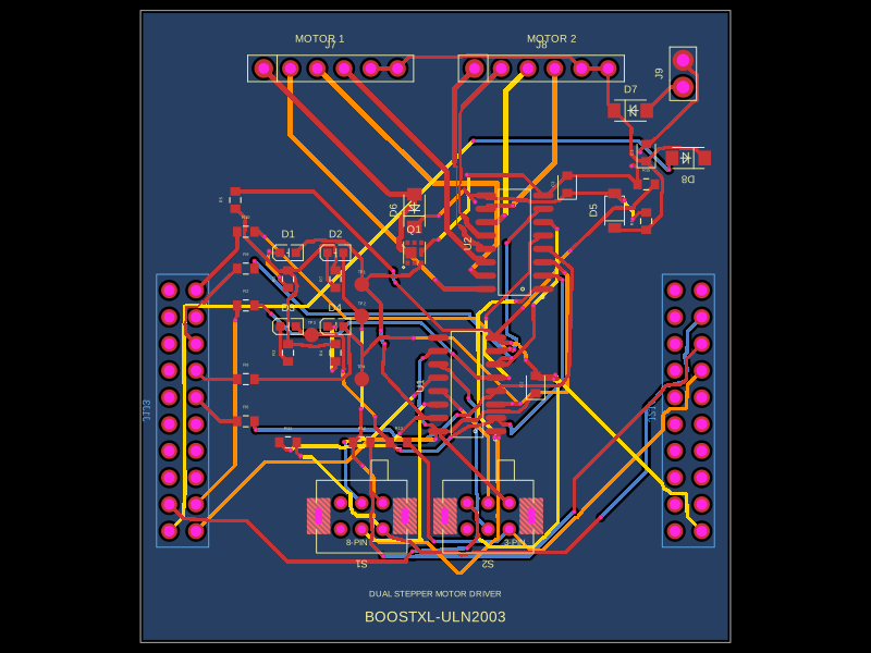 More from this authorabse/boostxl-uln2003This code defines a React component that models a through-hole or surface-mount LED with specified pin labels, footprint, silkscreen, and 3D CAD model for PCB layout.
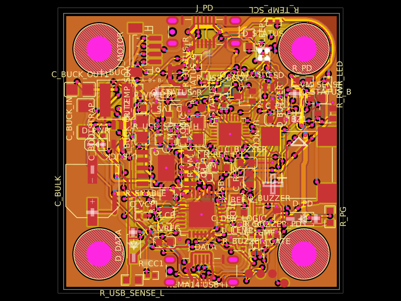 Discover something newAnasSarkiz/NEMA14_CH32X035G8U6A NEMA stepper motor is shown with proposed M3 screws/spacers, four wired motor leads and splices, and a JST SHR-04V-S connector.