ShiboSoftwareDev/captivate-fr2676
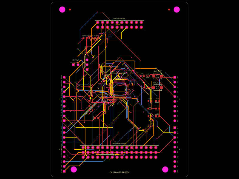
This circuit implements an MSP430FR2676 microcontroller-based development module with integrated power regulation, user interface components, programming interfaces, and sensor/boosterpack headers for embedded system prototyping.
- Version
- 1.0.0
- License
- unset
- Stars
- 0
README.md
PCB
# CAPTIVATE-FR2676 tscircuit edition

This project is a fabrication-output-ready, electrically usable tscircuit edition of TI's CAPTIVATE-FR2676 MSP430 evaluation module. It keeps the board's main functions: MSP430FR2676 target, 16 CapTIvate channels, grounded center sensor row, sensor-side I2C/GPIO/power, Spy-Bi-Wire programming, isolated UART/HID-I2C/IRQ/SYNC, selectable target power, three LEDs, a user button, reset, and the partially populated 40-pin BoosterPack provision.

The design uses tscircuit's default autorouter on four copper layers. Board constraints are a 0.15 mm minimum trace width, 0.30 mm minimum via hole, and 0.45 mm minimum via pad.

## Intentional implementation choices

- `U_TARGET` is the TI-supported 48-pin `MSP430FR2676TPT` TQFP variant. The TI EVM reference uses the 40-pin RHA VQFN variant, but repeated clean default-router runs on that dense footprint stalled or timed out in `highDensityRouteSolver`. The TPT device exposes the same required functions and produced a verifiable default-autorouted result.
- `J_PWRSEL` pins 1-2 select the normal `VCC_LDO` rail; pins 2-3 select `VCC_MEASURED`, following TI's functional power-selection scheme.
- The board does not include the CAPTIVATE-PGMR. A programmer, sensor panel, or external 3.3 V source is required as appropriate.
- The CAPTIVATE-PGMR and 48-pin sensor connectors have explicit logical pin labels in this project. TI's `SLAC789.ZIP` hardware archive and the guide's full-resolution schematic images returned HTTP 403 in this environment, so their physical pin numbering could not be independently audited. Treat these headers as labeled custom-cable interfaces and verify the mating connector drawing before plugging directly into an original TI ecosystem board.
- This is a functional tscircuit edition, not a dimensionally exact clone of the TI PCB. The schematic is organized into two sheets matching the reference's core/user and interface groupings.

## Verification

The published `dist` artifacts were generated with the project-local current tscircuit dependency.

- Fresh default autoroute: 121 PCB traces, 165 routed vias, 0 router errors, 56.5 s
- Circuit JSON: 0 `*_error` elements
- `tsci check source`: 0 errors, 0 warnings
- `tsci check netlist`: 0 errors, 0 warnings
- `tsci check placement`: 0 errors; three connector-orientation heuristic warnings remain after visual inspection
- Gerber archive: top/bottom/inner1/inner2 copper, top/bottom mask and paste, silkscreen, outline, plated drill, NPTH drill, BOM, and PnP
- Plated drill: includes 0.300 mm routed vias
- `tsci check shorts --mode gerber --layer all`: no shorts at default resolution
- The same Gerber short check at 40 pixels/mm: no shorts

The generated PCB files are ready to quote and fabricate as this tscircuit edition. Direct mechanical/electrical mating with TI's CAPTIVATE-PGMR or sensor panels remains conditional on verifying the physical connector pin order noted above.

## Build and inspect

```sh
bun install
bun run typecheck
bun run build -- --autorouter-timeout 180000
bun run render
./node_modules/.bin/tsci export index.circuit.tsx --format gerbers --output dist/gerbers.zip
./node_modules/.bin/tsci check shorts dist/index/circuit.json --mode gerber --layer all
./node_modules/.bin/tsci check shorts dist/index/circuit.json --mode gerber --layer all --pixels-per-mm 40
```