PatanSharuKhan/blinking-led-board
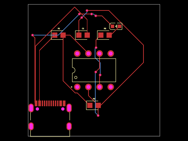
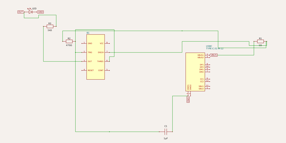
A USB-powered 555 timer-based blinking red LED circuit with multiple resistors and a capacitor for timing control.
Usage: To import and use the blinking LED board component: 1. Import the component: ```tsx import { MyBlinkingLedCircuit } from "@tsci/PatanSharuKhan.blinking-led-board" ``` 2. Use in a React component: ```tsx export default () => ( <MyBlinkingLedCircuit /> ) ``` The component creates a complete blinking LED circuit using a USB-C power source, NE555P timer, resistors, capacitor, and a red LED, with automatic schematic layout.
- Version
- 0.0.1
- License
- unset
- Stars
- 1
index.tsx
PCB
Schematic
import { useUsbC } from "@tsci/seveibar.smd-usb-c"
import { useRedLed } from "@tsci/seveibar.red-led"
import { useNE555P } from "@tsci/seveibar.a555timer"

export const MyBlinkingLedCircuit = () => {
  const USBC = useUsbC("USBC")
  const Led = useRedLed("LED")
  const A555Timer = useNE555P("B1")

  return (
    <board width="30mm" height="30mm" schAutoLayoutEnabled>
      <USBC GND1="net.GND" VBUS1="net.VBUS" pcbX={-10} pcbY={-10} />
      <A555Timer
        name="B1"
        pin8="net.VBUS"
        pin1="net.GND"
        pin3="net.OUT"
        pin2="net.TRIG"
        pin6="net.THRES"
        pin7="net.DIS"
      />
      <resistor name="R1" resistance="1K" footprint="0805" pcbX={-8} pcbY={8} />
      <resistor
        name="R2"
        resistance="470K"
        footprint="0805"
        pcbX={0}
        pcbY={-8}
      />
      <resistor
        name="R3"
        resistance="1k"
        footprint="0805"
        pcbX={2.5}
        pcbY={8}
      />

      <capacitor
        name="C1"
        capacitance="1uF"
        footprint="0805"
        pcbX={-2.5}
        pcbY={8}
      />

      <Led pos="net.OUT" neg="net.GND" pcbX={5} pcbY={10} />

      <trace from=".USBC > .VBUS1" to=".R1 > .left" />
      <trace from=".R1 > .right" to=".R2 > .left" />
      <trace from=".R2 > .right" to=".C1 > .left" />
      <trace from=".C1 > .right" to=".USBC > .GND1" />
      <trace from=".B1 > .pin7" to=".R1 > .right" />
      <trace from=".B1 > .pin6" to=".R2 > .right" />
      <trace from=".B1 > .pin2" to=".R2 > .right" />
      <trace from=".B1 > .pin3" to=".R3 > .left" />
      <trace from=".R3 > .right" to=".LED > .pos" />
    </board>
  )
}