MustafaMulla29/stride-pedometer
This code defines schematic symbols and 3D footprints for various hardware components such as antennas, sensors, regulators, and connectors used in electronic circuit design.
- Version
- 1.0.4
- License
- unset
- Stars
- 0
docs/firmware-and-interfaces.md
# Firmware integration specification

This document specifies the firmware required by Rev A. A flashable CC2340R5 application and phone app are not included. Use TI's CC2340R5 BLE SDK for the radio stack and power management, and Bosch's BMA400 SensorAPI for accelerometer setup. Do not infer that the PCB has been programmed or bench tested.

## Bus cross-reference

All addresses below are seven-bit I²C addresses. The shared bus uses 10 kΩ pullups to the always-on 3 V rail; begin at 100 kHz and check rise time on the built board. The OLED uses a separate software I²C bus with 4.7 kΩ pullups to its switched supply.

| Device | Board pins | Address | Interface choice |
|---|---|---|---|
| BMA400 | SDX→SDA, SCX→SCL, SDO→GND, CSB→3 V | 0x14 | Supports I²C and SPI; Rev A straps I²C |
| BQ25150 | SDA / SCL; VIO at 3 V | 0x6B | Raise LP and allow wake time before access |
| BQ27427 | SDA / SCL; external pullups at 3 V | 0x55 | Configure for the actual cell |
| SSD1306 glass | flex pin 11 SDA / pin 10 SCL | 0x3C | This particular 14-pin glass exposes I²C, not SPI |

Switching the BMA400 to SPI would require rerouting CSB, SDX, SCX, and SDO. A generic SSD1306 controller supports other interfaces, but they are not exposed by this glass; a different flex pinout would require a PCB revision.

## MCU pin allocation

| Function | CC2340R5 DIO | Physical QFN pin |
|---|---:|---:|
| Shared I²C SDA | 8 | 2 |
| Shared I²C SCL | 6 | 32 |
| Accelerometer INT1 / INT2 | 9 / 10 | 3 / 4 |
| Charger LP | 11 | 5 |
| Charger CE, active low | 12 | 6 |
| Charger INT | 13 | 7 |
| Gauge GPOUT | 14 | 9 |
| Charger PG / button | 15 | 10 |
| SWDIO / SWCLK | 16 / 17 | 11 / 12 |
| OLED SCL / SDA | 18 / 19 | 13 / 14 |
| OLED reset, active low | 20 | 15 |
| Boost enable | 21 | 16 |
| 32 kHz crystal | 3 / 4 | 26 / 27 |
| MCU reset | — | 25 |

Configure SDA/SCL as open-drain. Disable internal pulls on the display bus when its rail is off. Unused DIOs should have deliberate low-leakage input/output states. Do not poll the accelerometer at its sample rate: the sensor counts steps without waking the MCU for every sample or every step.

## Charger boot values for the provisional 100 mAh cell

Keep CE high and boost low before any register writes. Verify all writes before driving CE low. These values assume a standard 4.2 V cell that accepts 20 mA charge; cell selection remains a prerequisite to charging.

| Register | Address | Setting |
|---|---:|---|
| VBAT_CTRL | 0x12 | 0x3C: 4.2 V |
| ICHG_CTRL | 0x13 | 0x10: 20 mA in the low-current range |
| PCHRGCTRL | 0x14 | 0x02: low-current range, 2.5 mA precharge |
| CHARGERCTRL0 | 0x17 | Set bit 4 to disable the register-reset watchdog; retain TS and the charging safety timer |
| ILIMCTRL | 0x19 | 0x01: 100 mA input limit |
| LDOCTRL | 0x1D | 0x60: 3 V configured and off; 0xE0: 3 V on |
| ICCTRL1 | 0x36 | Set PG_MODE bits 3:2 to 01 for the level-shifted button; retain PMID supply mode 00 |

Review termination-current and safety-timer settings against the selected cell. The hardware default charge current is 10 mA, but firmware must not rely on defaults. Raising LP and servicing I²C is distinct from asserting CE. On configuration or bus errors, leave charging disabled. Drive CE high whenever running from battery without a valid dock input. Holding CE low sinks 300 µA through its 10 kΩ pullup and would defeat the standby budget.

## Step counter and application behavior

Check the BMA400 chip ID, configure normal mode and the low-power step-counter settings through the Bosch driver, then enable its hardware step counter. The reset tuning is for wrist wear; use Bosch's documented non-wrist settings for a pocket device. Read its 24-bit count at 0x15–0x17 as a coherent burst. Handle wraparound and sensor resets separately, and accumulate into a 32-bit or 64-bit application total. Do not treat a sensor reset as millions of new steps.

Wake periodically, for example once per minute, to update the stored count. Wake on the button to display steps and battery percentage for five seconds. Keep a timer-based, non-blocking OLED shutdown state so the MCU can sleep while VCC discharges. Persist a checkpoint infrequently with wear leveling, and distinguish lifetime steps from today's steps. Daily reset needs a valid date supplied by the phone; the board has no independent calendar source after complete loss of power.

Configure the BQ27427 design capacity, chemistry selection, termination voltage, and other cell-specific parameters using TI's technical reference procedure. Verify initialization and power-reset flags before exposing state of charge as valid. Read the gauge slowly enough to permit its low-power modes. No generic state-of-charge curve can replace cell-specific setup and learning.

## Suggested BLE contract

Use the standard Battery Service for validated battery percentage. Add a custom service `aaac0001-6e2d-4b6f-9cf4-8fe80d38a001` with a read/notify characteristic `aaac0002-6e2d-4b6f-9cf4-8fe80d38a001` carrying `uint32 little-endian daily_steps`. These are proposed application UUIDs, not Bluetooth SIG assignments. Add a separate authenticated time/configuration characteristic if needed.

Start with advertising every two seconds when disconnected. Negotiate a long connection interval and peripheral latency for occasional sync, and notify only when useful. Use short fast-advertising windows after a button press. Measure the actual BLE stack's event duration and current; the power estimate is not a guarantee of the SDK's defaults.

This service can initially be exercised with a generic BLE inspection app. A dedicated phone app can follow after the hardware and GATT behavior are stable.
Related Packages
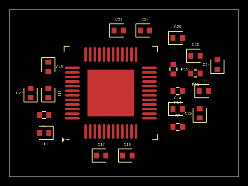 More from this authorMustafaMulla29/ti-chipThis code models a hardware circuit for a motor driver using a DRV83053QPHPQ1 integrated circuit, with power supply bypass capacitors, charge-pump capacitors, resistors, and filters, representing the physical connections and key components in a motor control power stage.
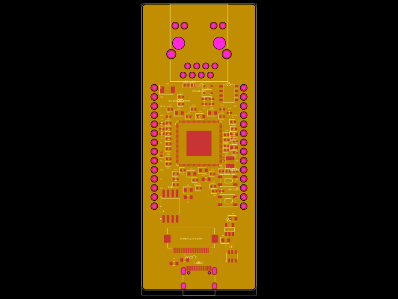 Similar packagemohan-bee/RV1106G2This code defines a detailed hardware schematic with schematic symbols, footprints, and 3D models for various electronic components including microcontrollers, voltage regulators, connectors, and passive parts, designed for PCB layout and routing.
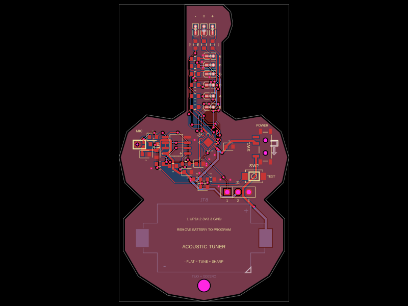 Discover something newgokul/acoustic-guitar-tunerThis code defines the physical pin configuration and footprint layouts for the ATtiny1616 microcontroller and a matching tactile switch component, including their key hardware connection points, dimensions, and 3D models.