MrPicklePinosaur/tscircuit_demo
This circuit hardware provides a USB-to-multi-protocol (I2C/SPI/UART) bridge using an FT232H chip, powered via a 3.3V regulator, with USB-C input, ESD protection, status LEDs, a STEMMA QT connector, and various support components.
Usage: To use this component in a project: 1. Import the specific component: ```tsx import { AMS1117_3_3 } from "@tsci/MrPicklePinosaur.tscircuit_demo/imports/AMS1117_3_3" ``` 2. Use the component in a board layout: ```tsx <board> <AMS1117_3_3 name="U2" /> </board> ``` Key details: - The component has predefined pin labels: - pin1: GND - pin2: VOUT1 - pin3: VIN - pin4: VOUT2 - Supports common layout props - Has a specific SMT footprint - Includes JLCPCB supplier part number (C6186)
- Version
- 1.0.0
- License
- unset
- Stars
- 0
dist/index.d.ts
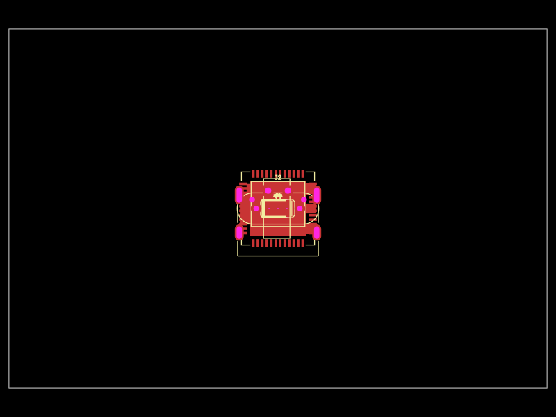
PCB
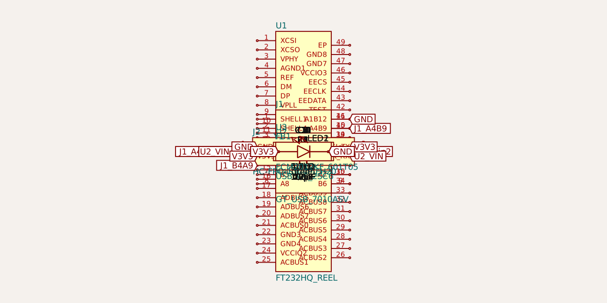
Schematic
/**
 * FT232H USB-to-Multi-Protocol Carrier Board
 *
 * Features:
 * - FTDI FT232H USB bridge (QFN-48 package)
 * - USB-C input (UFP device mode)
 * - 3.3V regulated power rail
 * - STEMMA QT connector (shared I2C/SPI/UART - software configurable)
 * - GPIO header for additional FT232H pins
 * - ESD protection on USB
 * - Status LEDs
 * - Test points for debugging
 *
 * IMPORTANT: FT232H can only operate in ONE mode at a time:
 * - I2C mode: SCL=ADBUS0, SDA=ADBUS1+ADBUS2 (needs external pull-ups)
 * - SPI mode: SCK=ADBUS0, MOSI=ADBUS1, MISO=ADBUS2, CS=ADBUS3+
 * - UART mode: TX=ADBUS0, RX=ADBUS1
 */
declare const _default: () => any;

export { _default as default };