Ayushjhawar8/stepper-mini-motor
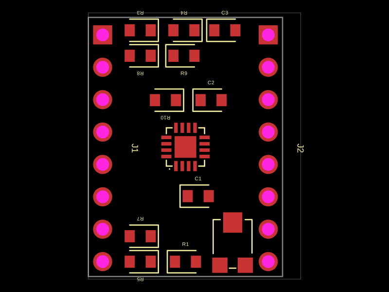
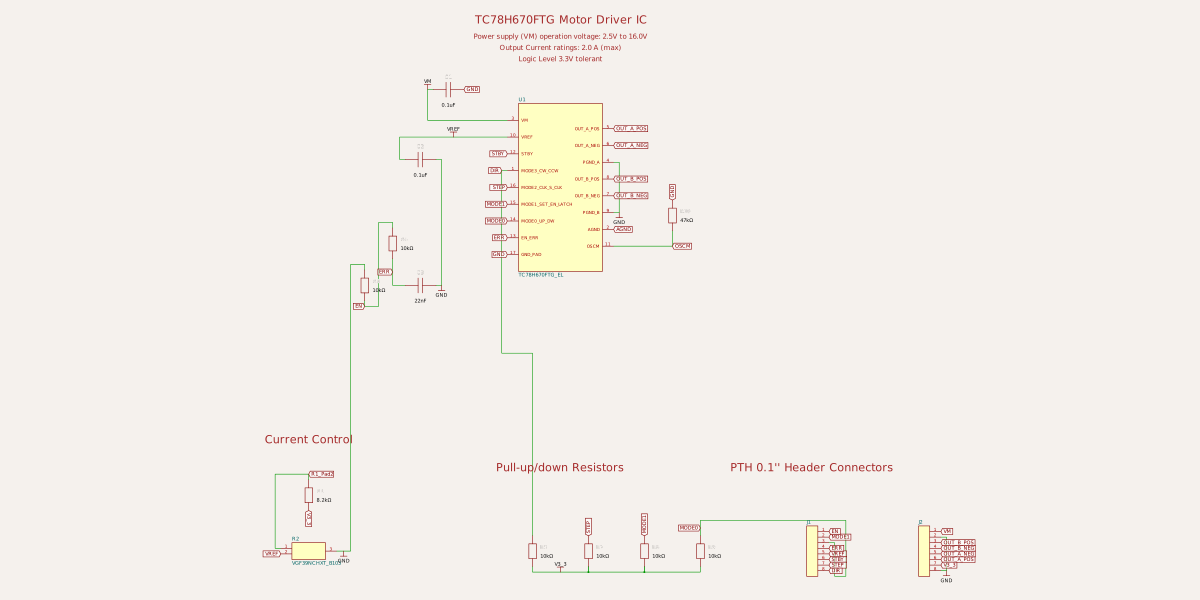
This code defines a schematic and PCB layout for a motor driver IC (TC78H670FTG) with associated passive components, power supply capacitors, resistors, headers, and mechanical footprints, all mapped with specific pin configurations and connections.
Usage: To use the stepper motor driver components in a tscircuit project: 1. Import the components: ```tsx import { TC78H670FTG_EL } from "@tsci/Ayushjhawar8.stepper-mini-motor" import { VGF39NCHXT_B103 } from "@tsci/Ayushjhawar8.stepper-mini-motor" ``` 2. Add components to your board with optional positioning and connections: ```tsx <TC78H670FTG_EL name="U1" pcbX={0} pcbY={0} connections={{ pin3: sel.net().VM, pin5: sel.net().OUT_A_POS, // other pin connections }} /> <VGF39NCHXT_B103 name="R2" pcbX={3.7} pcbY={-7.5} connections={{ pin2: sel.net().VREF, // other pin connections }} /> ``` The components come pre-configured with pin labels, footprints, and CAD models.
- Version
- 1.0.2
- License
- unset
- Stars
- 0
index.tsx
PCB
Schematic
import { sel } from "tscircuit";
import { TC78H670FTG_EL } from "./imports/TC78H670FTG_EL";
import { VGF39NCHXT_B103 } from "./imports/VGF39NCHXT_B103";

export default () => (
  <board width="15.24mm" height="20.32mm" routingDisabled>
    <schematictext
      text="TC78H670FTG Motor Driver IC"
      fontSize={0.4}
      color="brown"
      schY={6}
      schX={0}
    />
    <schematictext
      text="Power supply (VM) operation voltage: 2.5V to 16.0V"
      fontSize={0.25}
      color="brown"
      schY={5.4}
      schX={0}
    />
    <schematictext
      text="Output Current ratings: 2.0 A (max)"
      fontSize={0.25}
      color="brown"
      schY={5}
      schX={0}
    />
    <schematictext
      text="Logic Level 3.3V tolerant"
      fontSize={0.25}
      color="brown"
      schY={4.6}
      schX={0}
    />

    <TC78H670FTG_EL
      name="U1"
      pcbX={0}
      pcbY={0}
      pcbRotation={90}
      schX={0}
      schY={0}
      schWidth={3}
      schHeight={6}
      schPinSpacing={0.6}
      schPinArrangement={{
        leftSide: {
          direction: "top-to-bottom",
          pins: [3, 10, 12, 1, 16, 15, 14, 13, 17],
        },
        rightSide: {
          direction: "top-to-bottom",
          pins: [5, 6, 4, 8, 7, 9, 2, 11],
        },
      }}
      connections={{
        pin1: sel.net().DIR,
        pin2: sel.net().AGND,
        pin3: sel.net().VM,
        pin4: sel.net().GND,
        pin5: sel.net().OUT_A_POS,
        pin6: sel.net().OUT_A_NEG,
        pin7: sel.net().OUT_B_NEG,
        pin8: sel.net().OUT_B_POS,
        pin9: sel.net().GND,
        pin10: sel.net().VREF,
        pin11: sel.net().OSCM,
        pin12: sel.net().STBY,
        pin13: sel.net().ERR,
        pin14: sel.net().MODE0,
        pin15: sel.net().MODE1,
        pin16: sel.net().STEP,
        pin17: sel.net().GND,
      }}
    />

    {/* Power Supply Capacitors */}
    <capacitor
      name="C1"
      capacitance="0.1uF"
      footprint="0603"
      pcbX={1}
      pcbY={-3.857}
      pcbRotation={0}
      schRotation={0}
      schX={-4}
      schY={3.5}
      connections={{
        pin1: sel.net().VM,
        pin2: sel.net.GND,
      }}
    />

    <capacitor
      name="C2"
      capacitance="0.1uF"
      footprint="0603"
      pcbX={2.01}
      pcbY={3.67}
      pcbRotation={0}
      schRotation={0}
      schX={-5}
      schY={1}
      connections={{
        pin1: sel.net().VREF,
        pin2: sel.net.GND,
      }}
    />

    <capacitor
      name="C3"
      capacitance="22nF"
      footprint="0603"
      pcbX={3.09}
      pcbY={9.15}
      pcbRotation={0}
      schRotation={0}
      schX={-5}
      schY={-3.5}
      connections={{
        pin1: sel.net().ERR,
        pin2: sel.net.GND,
      }}
    />

    {/* Current Control Section */}
    <schematictext
      text="Current Control"
      fontSize={0.4}
      color="brown"
      schY={-9}
      schX={-9}
    />

    <resistor
      name="R1"
      resistance="8.2k"
      footprint="0603"
      pcbX={0}
      pcbY={-9}
      pcbRotation={0}
      schRotation={90}
      schX={-9}
      schY={-11}
      connections={{
        pin1: sel.net.V3_3,
        pin2: sel.net()["R1_Pad2"],
      }}
    />

    <VGF39NCHXT_B103
      name="R2"
      pcbX={3.7}
      pcbY={-7.5}
      pcbRotation={-90}
      schX={-9}
      schY={-13}
      connections={{
        pin1: sel.net()["R1_Pad2"],
        pin2: sel.net().VREF,
        pin3: sel.net.GND,
      }}
    />


    <schematictext
      text="Pull-up/down Resistors"
      fontSize={0.4}
      color="brown"
      schY={-10}
      schX={0}
    />

    <resistor
      name="R3"
      resistance="10k"
      footprint="0603"
      pcbX={-3.55}
      pcbY={9.15}
      pcbRotation={180}
      schRotation={90}
      schX={-7}
      schY={-3.5}
      connections={{
        pin1: sel.net().EN,
        pin2: sel.net.GND
      }}
    />

    <resistor
      name="R4"
      resistance="10k"
      footprint="0603"
      pcbX={-0.12}
      pcbY={9.15}
      pcbRotation={180}
      schRotation={90}
      schX={-6}
      schY={-2}
      connections={{
        pin1: sel.net().ERR,
        pin2: sel.net().EN,
      }}
    />

    <resistor
      name="R5"
      resistance="10k"
      footprint="0603"
      pcbX={-3.55}
      pcbY={-9}
      pcbRotation={180}
      schRotation={90}
      schX={-1}
      schY={-13}
      connections={{
        pin1: sel.net.V3_3,
        pin2: sel.net().DIR,
      }}
    />

    <resistor
      name="R7"
      resistance="10k"
      footprint="0603"
      pcbX={-3.55}
      pcbY={-7}
      pcbRotation={180}
      schRotation={90}
      schX={1}
      schY={-13}
      connections={{
        pin1: sel.net.V3_3,
        pin2: sel.net().STEP,
      }}
    />

    <resistor
      name="R8"
      resistance="10k"
      footprint="0603"
      pcbX={-3.55}
      pcbY={7.15}
      pcbRotation={180}
      schRotation={90}
      schX={3}
      schY={-13}
      connections={{
        pin1: sel.net.V3_3,
        pin2: sel.net().MODE1,
      }}
    />

    <resistor
      name="R9"
      resistance="10k"
      footprint="0603"
      pcbX={-0.12}
      pcbY={7.15}
      pcbRotation={0}
      schRotation={90}
      schX={5}
      schY={-13}
      connections={{
        pin1: sel.net.V3_3,
        pin2: sel.net().MODE0,
      }}
    />

    <resistor
      name="R10"
      resistance="47k"
      footprint="0603"
      pcbX={-1.568}
      pcbY={3.67}
      pcbRotation={180}
      schRotation={90}
      schX={4}
      schY={-1}
      connections={{
        pin1: sel.net().OSCM,
        pin2: sel.net().GND,
      }}
    />

    {/* PTH 0.1" Header Connectors */}
    <schematictext
      text="PTH 0.1'' Header Connectors"
      fontSize={0.4}
      color="brown"
      schY={-10}
      schX={9}
    />

    <pinheader
      name="J1"
      pinCount={8}
      pcbX={-6.5}
      pcbY={-0.1}
      pcbRotation={270}
      schPinArrangement={{
        leftSide: {
          direction: "top-to-bottom",
          pins: [1, 2, 3, 4, 5, 6, 7, 8],
        },
      }}
      schX={9}
      schY={-13}
      connections={{
        pin1: sel.net().EN,
        pin2: sel.net().MODE1,
        pin3: sel.net().MODE0,
        pin4: sel.net().ERR,
        pin5: sel.net().VREF,
        pin6: sel.net().STBY,
        pin7: sel.net().STEP,
        pin8: sel.net().DIR,
      }}
    />

    <pinheader
      name="J2"
      pinCount={8}
      pcbX={6.5}
      pcbY={-0.1}
      pcbRotation={270}
      schPinArrangement={{
        leftSide: {
          direction: "top-to-bottom",
          pins: [1, 2, 3, 4, 5, 6, 7, 8],
        },
      }}
      schX={13}
      schY={-13}
      connections={{
        pin1: sel.net().VM,
        pin2: sel.net().GND,
        pin3: sel.net().OUT_B_POS,
        pin4: sel.net().OUT_B_NEG,
        pin5: sel.net().OUT_A_NEG,
        pin6: sel.net().OUT_A_POS,
        pin7: sel.net.V3_3,
        pin8: sel.net().GND,
      }}
    />

  </board>
);