AnasSarkiz/usb-c-pwm-pa25
A component library defining an AO3400A N-channel MOSFET, 47 µF polarized capacitor, 3-pin through-hole connector, and 9.1 V Zener diode with PCB footprints and 3D CAD models.
- Version
- 0.1.0-prototype.2
- License
- unset
- Stars
- 0
lib/user-controls.tsx
import { SchematicNote } from "./schematic-note";
import { B3B_PH_K_S_LF__SN_ } from "../imports/B3B_PH_K_S_LF__SN_";
import { LTST_C190TBKT } from "../imports/LTST_C190TBKT";
import { LTST_C190KGKT } from "../imports/LTST_C190KGKT";
import { LTST_C190KRKT } from "../imports/LTST_C190KRKT";
import { C, R } from "./passives";

export function UserControls() {
	return (
		<schematicsheet
			name="controls"
			displayName="06 Knob, FWD / STOP / REV, indicators — A1 prototype"
			sheetSize="A4"
			sheetIndex={5}
		>
			<B3B_PH_K_S_LF__SN_
				name="J3"
				pcbX={-27}
				pcbY={26}
				schX={-8}
				schY={5}
				connections={{
					pin1: "net.GND",
					pin2: "net.POT_WIPER",
					pin3: "net.V3V3",
				}}
			/>
			<R
				name="R60"
				resistance="1k"
				pcb={[-27, 19]}
				sch={[-8, 1]}
				nets={["POT_WIPER", "POT_ADC"]}
			/>
			<R
				name="R61"
				resistance="100k"
				pcb={[-23, 19]}
				sch={[-8, -2]}
				nets={["POT_ADC", "GND"]}
			/>
			<C
				name="C50"
				capacitance="100nF"
				pcb={[-23, 16.5]}
				sch={[-8, -5]}
				nets={["POT_ADC", "GND"]}
			/>
			<B3B_PH_K_S_LF__SN_
				name="J4"
				pcbX={-11}
				pcbY={26}
				schX={2}
				schY={5}
				connections={{ pin1: "net.FWD", pin2: "net.GND", pin3: "net.REV" }}
			/>
			<R
				name="R62"
				rotation={180}
				resistance="10k"
				pcb={[-13, 19]}
				sch={[0, 1]}
				nets={["V3V3", "FWD"]}
			/>
			<R
				name="R63"
				resistance="10k"
				pcb={[-9, 19]}
				sch={[5, 1]}
				nets={["V3V3", "REV"]}
			/>
			<C
				name="C51"
				capacitance="100nF"
				pcb={[-13, 16.5]}
				sch={[0, -2]}
				nets={["FWD", "GND"]}
			/>
			<C
				name="C52"
				rotation={180}
				capacitance="100nF"
				pcb={[-9, 16.5]}
				sch={[5, -2]}
				nets={["REV", "GND"]}
			/>
			<SchematicNote
				schX={0}
				schY={9}
				fontSize={0.23}
				text={
					"Panel controls: J3 → 10 kΩ linear pot; J4 → maintained SPDT center-OFF switch.\nSTOP = both contacts open; both closed is a fault. Debounce in firmware.\nStartup/reconnect requires STOP and knob below 2%, then a deliberate direction selection.\nOpen pot wiper pulls command to zero. Control cables ≤150 mm inside enclosure."
				}
			/>
			<R
				name="R64"
				resistance="1k"
				pcb={[-33, -22]}
				sch={[-8, -7]}
				nets={["V3V3", "LED_PWR_A"]}
			/>
			<LTST_C190TBKT
				name="D3"
				color="blue"
				pcbX={-33}
				pcbY={-25}
				schX={-8}
				schY={-9.5}
				schRotation={-90}
				connections={{ anode: "net.LED_PWR_A", cathode: "net.GND" }}
			/>
			<R
				name="R65"
				schRotation={-90}
				resistance="1k"
				pcb={[-26, -22]}
				sch={[0, -7]}
				nets={["LED_READY", "LED_READY_A"]}
			/>
			<LTST_C190KGKT
				name="D4"
				color="green"
				pcbX={-26}
				pcbY={-25}
				schX={0}
				schY={-9.5}
				schRotation={-90}
				connections={{ anode: "net.LED_READY_A", cathode: "net.GND" }}
			/>
			<R
				name="R66"
				schRotation={-90}
				resistance="1k"
				pcb={[-19, -22]}
				sch={[8, -7]}
				nets={["LED_FAULT", "LED_FAULT_A"]}
			/>
			<LTST_C190KRKT
				name="D5"
				color="red"
				pcbX={-19}
				pcbY={-25}
				schX={8}
				schY={-9.5}
				schRotation={-90}
				connections={{ anode: "net.LED_FAULT_A", cathode: "net.GND" }}
			/>
			<SchematicNote
				schX={2}
				schY={-4}
				fontSize={0.23}
				text={
					"Blue: control power present. Green: armed/ready or running.\nRed: latched fault; turn to STOP and set knob to zero.\nReversal requires ramp-down, coast and re-arming.\nOpen-loop duty control: speed depends on the mechanical load."
				}
			/>
		</schematicsheet>
	);
}
Related Packages
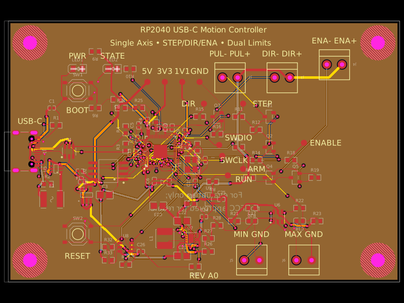 More from this authorAnasSarkiz/rp2040-usb-c-single-axis-dm542t-motion-controller--01a0e89cA USB‑C RP2040 controller board with external QSPI flash, crystal clock, regulated 3.3/1.1/5 V power, boost-converted motor-driver supply, protected USB and limit inputs, status LEDs, reset/boot switches, and AO3400A MOSFET outputs for stepper-control signals.
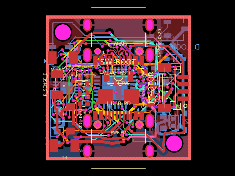 Similar packageShiboSoftwareDev/nema8-20mm-dual-usbc-stepper-controllerBAT54C is a compact three-pin SMD dual Schottky diode, while BAT54WS is a two-pin SMD single Schottky diode, each with defined PCB footprints and 3D models.
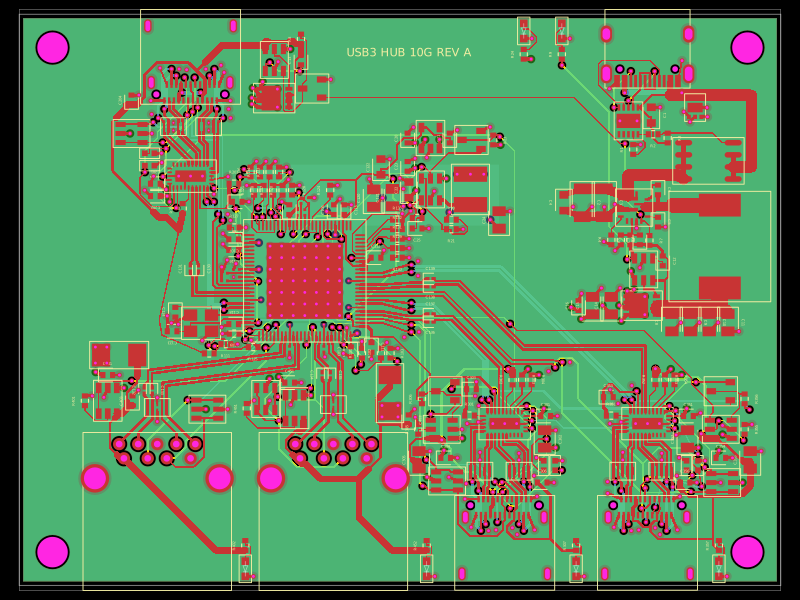 Discover something newpixalynx/usb3-hub-10gA USB 3.2 Gen 2 six-port hub board with USB-C PD power input, regulated 5 V/3.3 V/1.15 V rails, one upstream and four protected downstream USB-A/USB-C ports, SuperSpeed muxes, ESD protection, and controlled port power.