AnasSarkiz/usb-c-pwm-pa25
A component library defining an AO3400A N-channel MOSFET, 47 µF polarized capacitor, 3-pin through-hole connector, and 9.1 V Zener diode with PCB footprints and 3D CAD models.
- Version
- 0.1.0-prototype.2
- License
- unset
- Stars
- 0
lib/motor-power.tsx
import { A_25SVPF47M } from "../imports/A_25SVPF47M";
import { SchematicNote } from "./schematic-note";
import { AO3400A } from "../imports/AO3400A";
import { TPS259470LRPWR } from "../imports/TPS259470LRPWR";
import { TPS54202DDCR } from "../imports/TPS54202DDCR";
import { SRP7050TA_150M } from "../imports/SRP7050TA_150M";
import { C, R, TestPad } from "./passives";

export function MotorPower() {
	return (
		<schematicsheet
			name="power"
			displayName="02 Protected 15 V / regulated 12 V — A1 prototype"
			sheetSize="A4"
			sheetIndex={1}
		>
			<TPS259470LRPWR
				name="U2"
				pcbX={-15}
				pcbY={2}
				schX={-8}
				schY={5}
				connections={{
					IN: "net.PD_OUT",
					OUT: "net.V15",
					GND: "net.GND",
					EN_UVLO: "net.INPUT_EN",
					OVLO: "net.INPUT_OV",
					DVDT: "net.INPUT_SLEW",
					ILM: "net.INPUT_LIMIT",
					AUXOFF: "net.HEALTH",
					FLT: "net.HEALTH",
				}}
				noConnect={["ITIMER"]}
			/>
			<SchematicNote
				schX={-8}
				schY={9}
				fontSize={0.23}
				text={
					"U2: 2.7–23 V eFuse; 1.19 A nominal limit; latched faults.\nUV ≈13.2 V / OV ≈16.8 V. 0.2 V/ms soft start.\nQ2 defaults ON to inhibit power until a valid PD contract."
				}
			/>
			<R
				name="R10"
				resistance="100k"
				pcb={[-20, 6]}
				sch={[-13, 5]}
				nets={["PD_OUT", "INPUT_EN"]}
			/>
			<R
				name="R11"
				resistance="10k"
				pcb={[-16, 6]}
				sch={[-13, 2.5]}
				nets={["INPUT_EN", "GND"]}
			/>
			<R
				name="R12"
				resistance="130k"
				pcb={[-20, 8.5]}
				sch={[-3, 5]}
				nets={["PD_OUT", "INPUT_OV"]}
			/>
			<R
				name="R13"
				resistance="10k"
				pcb={[-16, 8.5]}
				sch={[-3, 2.5]}
				nets={["INPUT_OV", "GND"]}
			/>
			<R
				name="R14"
				resistance="2.8k"
				pcb={[-11, 6]}
				sch={[-13, 0]}
				nets={["INPUT_LIMIT", "GND"]}
			/>
			<C
				name="C10"
				capacitance="10nF"
				pcb={[-11, 3.5]}
				sch={[-8, 0]}
				nets={["INPUT_SLEW", "GND"]}
			/>
			<C
				name="C11"
				capacitance="100nF"
				pcb={[-19, -0.5]}
				sch={[-3, 0]}
				nets={["PD_OUT", "GND"]}
			/>
			<AO3400A
				name="Q2"
				pcbX={-15}
				pcbY={-3}
				schX={-8}
				schY={-3}
				connections={{ G: "net.PWR_OFF", S: "net.GND", D: "net.INPUT_EN" }}
			/>
			<R
				name="R15"
				resistance="10k"
				pcb={[-19, -4]}
				sch={[-13, -3]}
				nets={["V3V3", "PWR_OFF"]}
			/>
			<TPS54202DDCR
				name="U4"
				pcbX={-4}
				pcbY={2}
				schX={7}
				schY={5}
				connections={{
					VIN: "net.V15",
					GND: "net.GND",
					SW: "net.SW",
					BOOT: "net.BOOT",
					FB: "net.FB",
				}}
				noConnect={["EN"]}
			/>
			<SchematicNote
				schX={7}
				schY={9}
				fontSize={0.23}
				text={
					"U4: TPS54202 buck, 15 V → 11.980 V nominal; 500 kHz.\nInput 4.5–28 V; IC 2 A rating is not a board rating.\n15 µH / 47 µF polymer; FB = 191 kΩ / 10 kΩ; EN internally pulled up."
				}
			/>
			<C
				name="C12"
				capacitance="10uF"
				pcb={[-6, -2]}
				sch={[2, 5]}
				nets={["V15", "GND"]}
			/>
			<C
				name="C13"
				capacitance="100nF"
				pcb={[-8, 1.7]}
				sch={[2, 2.5]}
				nets={["V15", "GND"]}
			/>
			<C
				name="C14"
				capacitance="100nF"
				pcb={[-4, 5.5]}
				sch={[7, 0]}
				nets={["BOOT", "SW"]}
			/>
			<SRP7050TA_150M
				name="L1"
				pcbRotation={180}
				pcbX={3.5}
				pcbY={1}
				schX={12}
				schY={5}
				connections={{ pin1: "net.SW", pin2: "net.V12_BUCK" }}
			/>
			<A_25SVPF47M
				name="C15"
				pcbX={5}
				pcbY={-7}
				schX={12}
				schY={1.5}
				schRotation={-90}
				connections={{ pin1: "net.V12_BUCK", pin2: "net.GND" }}
			/>
			<C
				name="C16"
				capacitance="100nF"
				pcb={[11.5, -5]}
				sch={[12, -1]}
				nets={["V12_BUCK", "GND"]}
			/>
			<R
				name="R16"
				rotation={180}
				resistance="191k"
				pcb={[-2, -4.5]}
				sch={[2, -2]}
				nets={["V12_BUCK", "FB"]}
			/>
			<R
				name="R17"
				rotation={180}
				resistance="10k"
				pcb={[-2, -7]}
				sch={[7, -2]}
				nets={["FB", "GND"]}
			/>
			<C
				name="C19"
				capacitance="47pF"
				pcb={[-7, 5.5]}
				sch={[2, 0]}
				nets={["V12_BUCK", "FB"]}
			/>
			<TPS259470LRPWR
				name="U5"
				pcbX={12}
				pcbY={1}
				schX={0}
				schY={-7}
				connections={{
					IN: "net.V12_BUCK",
					OUT: "net.VM",
					GND: "net.GND",
					EN_UVLO: "net.MOTOR_UV",
					OVLO: "net.MOTOR_OV",
					DVDT: "net.MOTOR_SLEW",
					ILM: "net.MOTOR_LIMIT",
					AUXOFF: "net.HEALTH",
					FLT: "net.HEALTH",
				}}
				noConnect={["ITIMER"]}
			/>
			<R
				name="R18"
				resistance="80.6k"
				pcb={[10, 6]}
				sch={[-10, -6]}
				nets={["V12_BUCK", "MOTOR_UV"]}
			/>
			<R
				name="R19"
				resistance="10k"
				pcb={[14, 6]}
				sch={[-5, -6]}
				nets={["MOTOR_UV", "GND"]}
			/>
			<R
				name="R20"
				resistance="100k"
				pcb={[10, 8.5]}
				sch={[-10, -8.5]}
				nets={["V12_BUCK", "MOTOR_OV"]}
			/>
			<R
				name="R21"
				resistance="10k"
				pcb={[14, 8.5]}
				sch={[-5, -8.5]}
				nets={["MOTOR_OV", "GND"]}
			/>
			<R
				name="R22"
				resistance="2.8k"
				pcb={[16, 3]}
				sch={[5, -6]}
				nets={["MOTOR_LIMIT", "GND"]}
			/>
			<C
				name="C17"
				capacitance="10nF"
				pcb={[16, 0.5]}
				sch={[10, -6]}
				nets={["MOTOR_SLEW", "GND"]}
			/>
			<C
				name="C18"
				capacitance="100nF"
				pcb={[15, -3]}
				sch={[5, -8.5]}
				nets={["V12_BUCK", "GND"]}
			/>
			<AO3400A
				name="Q3"
				pcbX={12}
				pcbY={-10}
				schX={10}
				schY={-9}
				connections={{ G: "net.PWR_OFF", S: "net.GND", D: "net.MOTOR_UV" }}
			/>
			<SchematicNote
				schX={1}
				schY={-10.5}
				fontSize={0.23}
				text={
					"U5: continuous reverse-current blocking isolates regenerated VM from the buck.\nUV ≈10.872 V / OV ≈13.2 V; 1.19 A nominal limit. 470 µF bulk is downstream.\nHEALTH combines open-drain ready/fault signals; U2 disable resets both power stages."
				}
			/>
			<TestPad name="TP3" net="V15" pcb={[-9, -9]} sch={[-13, -9]} />
			<TestPad name="TP4" net="V12_BUCK" pcb={[5, -13]} sch={[13, -7.8]} />
		</schematicsheet>
	);
}
Related Packages
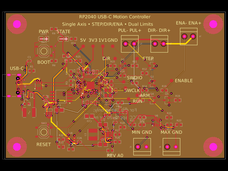 More from this authorAnasSarkiz/rp2040-usb-c-single-axis-dm542t-motion-controller--01a0e89cA USB‑C RP2040 controller board with external QSPI flash, crystal clock, regulated 3.3/1.1/5 V power, boost-converted motor-driver supply, protected USB and limit inputs, status LEDs, reset/boot switches, and AO3400A MOSFET outputs for stepper-control signals.
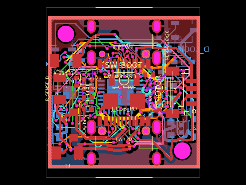 Similar packageShiboSoftwareDev/nema8-20mm-dual-usbc-stepper-controllerBAT54C is a compact three-pin SMD dual Schottky diode, while BAT54WS is a two-pin SMD single Schottky diode, each with defined PCB footprints and 3D models.
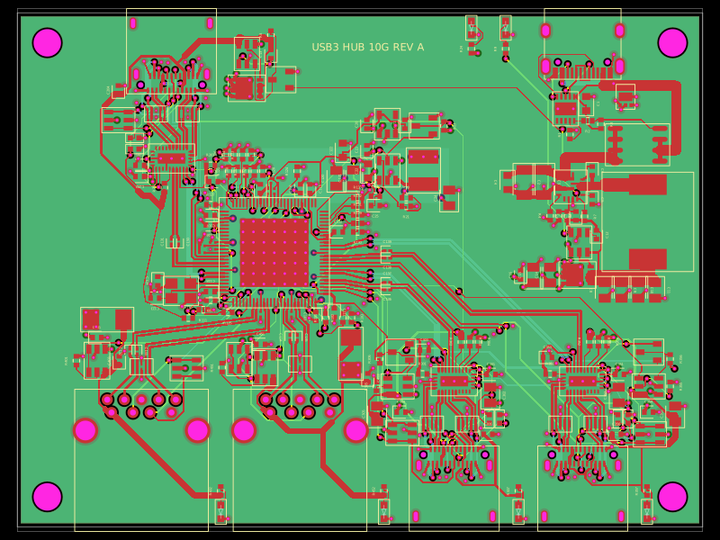 Discover something newpixalynx/usb3-hub-10gA USB 3.2 Gen 2 six-port hub board with USB-C PD power input, regulated 5 V/3.3 V/1.15 V rails, one upstream and four protected downstream USB-A/USB-C ports, SuperSpeed muxes, ESD protection, and controlled port power.