AnasSarkiz/usb-c-pwm-pa25
A component library defining an AO3400A N-channel MOSFET, 47 µF polarized capacitor, 3-pin through-hole connector, and 9.1 V Zener diode with PCB footprints and 3D CAD models.
- Version
- 0.1.0-prototype.2
- License
- unset
- Stars
- 0
docs/PROTOTYPE_TEST_PLAN.md
# Prototype test plan — not performed

Record physical board revision, source/dependency checksums, assembly substitutions, instruments, ambient/enclosure conditions, supply/cable model, load mechanism and all readings. A1 source and compiled firmware exist; no physical hardware has been tested.

## Before applying power

Check assembly/polarity/shorts, USB shell joints, exposed-pad soldering, mounting isolation and wire strain relief. Establish an emergency disconnect and guard moving parts. Start with the motor disconnected and an electronic load or resistor fixture. Check reference and regulator set points before connecting the motor.

## Power and controls

| Test | Required evidence |
|---|---|
| Fixed PD contract | Analyzer capture showing the requested and granted fixed 15 V contract and current; repeat for both cable orientations |
| Unsupported source | Default 5 V, insufficient-current PDO, no 15 V profile and negotiation failure: no motor drive |
| Hot plug and PD reset | Scope VBUS, protected rail, 12 V, enable and current; no unexpected pulse or automatic restart |
| Cable removal / brownout | Repeat at several knob positions and directions; require retained restart inhibition |
| Reconnection | Switch left in FWD or REV must remain disabled until deliberate STOP/zero re-arm |
| Inrush | Measure plug-in and bulk-charge peak/duration against the actual contract, limiter tolerance and charger behavior |
| Buck | Line/load regulation, ripple, dropout and startup overshoot with dummy load; inspect temperature |
| PWM | Frequency near 20 kHz, useful duty range, zero at minimum across knob tolerance, open-wiper stop |
| Direction control | Bounce and rapid FWD/REV commands; scope ramp, PWM, stored direction and inhibit; validate the load's stopping interval |
| Current regulation | Initially use a safe electrical load; measure tolerance, dynamic overshoot and IPROPI accuracy over supply and temperature |
| Sustained overload | Test the hardware current regulator and firmware 350 mA / 100 ms fault latch electrically before stressing a motor; fault must remain latched after driver recovery |
| Temperature | Heat the board sensor controllably; verify cutoff/reset, component temperatures and enclosure effect |
| Regeneration | Reproduce the defined load energy with guarded equipment; measure rail peak, dissipation current, resistor/FET temperature and cable-removed behavior |

## Motor test limits

Begin unloaded, with an independently current-limited source/fixture and the controller set to zero. Characterize normal startup with brief supervised attempts and cool-down observation before increasing demanded torque. Record peak, duration and steady current; do not call the 0.56 A setting a continuous motor limit.

**Do not conduct an intentional stall yet.** The manufacturer supplies no safe stall duration or winding-temperature model. First define a pulse-energy/time limit and stop criteria from manufacturer guidance or qualified motor characterization. The electrical dummy-load overload test can verify shutdown without locking the motor. Do not derive a safe stall duration from the gearbox torque rating.

Keep stage 7 pending until real measurements support the particular mechanism, load, duty cycle, ambient and enclosure. Rendered PCB images are not prototype photographs. The final operating limits must distinguish design intent from tested results.
Related Packages
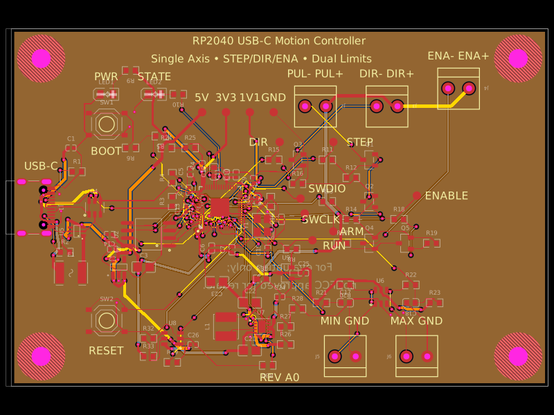 More from this authorAnasSarkiz/rp2040-usb-c-single-axis-dm542t-motion-controller--01a0e89cA USB‑C RP2040 controller board with external QSPI flash, crystal clock, regulated 3.3/1.1/5 V power, boost-converted motor-driver supply, protected USB and limit inputs, status LEDs, reset/boot switches, and AO3400A MOSFET outputs for stepper-control signals.
 Similar packageShiboSoftwareDev/nema8-20mm-dual-usbc-stepper-controllerBAT54C is a compact three-pin SMD dual Schottky diode, while BAT54WS is a two-pin SMD single Schottky diode, each with defined PCB footprints and 3D models.
 Discover something newpixalynx/usb3-hub-10gA USB 3.2 Gen 2 six-port hub board with USB-C PD power input, regulated 5 V/3.3 V/1.15 V rails, one upstream and four protected downstream USB-A/USB-C ports, SuperSpeed muxes, ESD protection, and controlled port power.