AnasSarkiz/rp2040-usb-c-single-axis-dm542t-motion-controller--01a0e89c
A USB‑C RP2040 controller board with external QSPI flash, crystal clock, regulated 3.3/1.1/5 V power, boost-converted motor-driver supply, protected USB and limit inputs, status LEDs, reset/boot switches, and AO3400A MOSFET outputs for stepper-control signals.
- Version
- 0.1.0-prototype.19
- License
- unset
- Stars
- 0
lib/output-mosfet.tsx
import { AO3400A } from "../imports/AO3400A"

// Preserve the catalog land pattern and pin geometry; add the missing refdes.
export function OutputMosfet(props: Parameters<typeof AO3400A>[0]) {
  return (
    <AO3400A
      {...props}
      symbol={
        <symbol>
          <schematictext
            text={props.name}
            schX={0.75}
            schY={0.2}
            fontSize={0.18}
          />
          <schematicpath
            points={[
              { x: 0, y: 0 },
              { x: 0.12, y: -0.04 },
              { x: 0.12, y: 0.04 },
              { x: 0, y: 0 },
            ]}
            strokeColor="#880000"
            isFilled
            fillColor="#FEFEFE"
          />
          <schematicpath
            points={[
              { x: 0.4, y: 0.04 },
              { x: 0.34, y: -0.06 },
              { x: 0.46, y: -0.06 },
              { x: 0.4, y: 0.04 },
            ]}
            strokeColor="#880000"
            isFilled
            fillColor="#FEFEFE"
          />
          <schematicpath
            points={[
              { x: 0, y: 0.14 },
              { x: 0.2, y: 0.14 },
              { x: 0.2, y: 0.2 },
              { x: 0.4, y: 0.2 },
              { x: 0.4, y: 0.04 },
            ]}
            strokeColor="#880000"
          />
          <schematicpath
            points={[
              { x: 0, y: 0 },
              { x: 0.2, y: 0 },
              { x: 0.2, y: -0.2 },
              { x: 0.4, y: -0.2 },
              { x: 0.4, y: -0.06 },
            ]}
            strokeColor="#880000"
          />
          <schematicpath
            points={[
              { x: 0.2, y: -0.14 },
              { x: 0, y: -0.14 },
            ]}
            strokeColor="#880000"
          />
          <schematicpath
            points={[
              { x: -0.04, y: 0.18 },
              { x: -0.04, y: -0.18 },
            ]}
            strokeColor="#880000"
          />
          <schematicpath
            points={[
              { x: 0, y: 0.18 },
              { x: 0, y: 0.1 },
            ]}
            strokeColor="#880000"
          />
          <schematicpath
            points={[
              { x: 0, y: -0.04 },
              { x: 0, y: 0.04 },
            ]}
            strokeColor="#880000"
          />
          <schematicpath
            points={[
              { x: 0, y: -0.18 },
              { x: 0, y: -0.1 },
            ]}
            strokeColor="#880000"
          />
          <schematicpath
            points={[
              { x: -0.2, y: 0 },
              { x: -0.04, y: 0 },
            ]}
            strokeColor="#880000"
          />
          <schematicpath
            points={[
              { x: 0.48, y: 0.04 },
              { x: 0.44, y: 0.04 },
              { x: 0.36, y: 0.04 },
              { x: 0.32, y: 0.04 },
            ]}
            strokeColor="#880000"
          />
          <port
            name="pin3"
            pinNumber={3}
            aliases={["D"]}
            direction="up"
            schX={0.2}
            schY={0.4}
            schStemLength={0.2}
          />
          <port
            name="pin1"
            pinNumber={1}
            aliases={["G"]}
            direction="left"
            schX={-0.4}
            schY={0}
            schStemLength={0.2}
          />
          <port
            name="pin2"
            pinNumber={2}
            aliases={["S"]}
            direction="down"
            schX={0.2}
            schY={-0.4}
            schStemLength={0.2}
          />
        </symbol>
      }
    />
  )
}
Related Packages
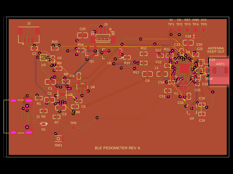 More from this authorAnasSarkiz/ble-pedometerThis code defines and configures various electronic hardware components such as surface-mount resistors, crystals, diodes, transistors, connectors, and switches with their physical footprints, schematic symbols, and 3D CAD models for PCB assembly.
 Similar packageaura/diy-power-delivery-triggerThis hardware design implements a USB Type-C port with supporting power management and signal conditioning components, including a USB-C connector, a FUSB302 USB-C port controller, ESD protection diodes, a buck converter for 3.3V power regulation, an STM32 microcontroller for control and processing, an RGB LED indicator, push button, terminal block connections, and associated filtering and support components.
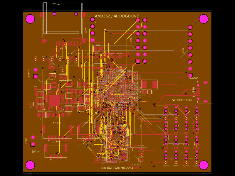 Discover something newseveibar/am3352-dev-board-4layer-dogboneDefines PCB footprints and pin mappings for a TI AM3352ZCZ100 processor, JST GH connectors, and assembly-part lookup helpers for capacitors, resistors, and headers.