AnasSarkiz/rp2040-usb-c-single-axis-dm542t-motion-controller--01a0e89c
A USB‑C RP2040 controller board with external QSPI flash, crystal clock, regulated 3.3/1.1/5 V power, boost-converted motor-driver supply, protected USB and limit inputs, status LEDs, reset/boot switches, and AO3400A MOSFET outputs for stepper-control signals.
- Version
- 0.1.0-prototype.19
- License
- unset
- Stars
- 0
STORE-LISTING.md
# RP2040 USB-C Single-Axis Stepper Motion Controller for External DM542T Drivers with STEP/DIR/ENABLE Outputs and Dual Limit-Switch Inputs

**Prototype source release 0.1.0-prototype.19 — revision A0 — untested. Four-layer routing validation failed; manufacturer acceptance pending. Not approved to order.**

A USB-powered RP2040 controller concept for one external STEPPERONLINE DM542T V4.0 driver, with buffered STEP/DIR/ENABLE signals, two normally-closed dry-contact limit inputs, USB bootloader access, SWD test pads, reset/boot buttons and status LEDs.

The 90 × 60 mm four-layer candidate uses four 3.2 mm NPTH mounting holes on an 80 × 50 mm pattern. Proposed firmware provides signed relative moves, speed, acceleration, stop, enable/disable, homing, heartbeat and status, with a 2000-step/s software cap and hardware-timed 10 µs STEP pulses.

The draft package contains tscircuit sources, an exact 85-component JLCPCB BOM, firmware sources and build instructions, software tests and a bring-up checklist. The power design includes a regulated 4.75 V driver rail, current limiting, brownout reset and USB suspend handling. The earlier routing pass missed via copper-spacing violations and is superseded. Label cleanup, manufacturing exports and function/rating notes for every IC are included. Through-hole stencil output, subtitle bullet rendering and printed legend dimensions are fixed and checked. Historical manufacturing packages are included for traceability and must not be ordered; assembler acceptance and physical testing remain outstanding. Actual USB suspend current remains unmeasured. Rendered views must be labeled renders; there are no physical board photos or measured hardware results.

Use the driver's 5 V input setting. No 24 V sensors or motor supply may connect to this board. Loss of controller power can leave the separately powered driver enabled and holding torque. Other driver revisions have not been validated. Intended limits are not measured operating specifications.

The user authorized GitHub and tscircuit source publication on 2026-09-29. This is a work-in-progress source package; fabrication and a sale-ready store release remain blocked by VALIDATION.md. No price, availability date, safety certification or hardware-tested claim is assigned.

Bottom silkscreen carries the requested notice: “For evaluation only; not FCC approved for resale.”

Prototype.19 adds eight native A4 schematic sheets, an eight-page landscape PDF and per-IC function/rating notes. Local routed dist and exact check results accompany the source. Routing and fabrication acceptance remain blocked; do not fabricate.

Current prototype.19 routing result: **84 native DRC errors**, 29 native shorts findings and three independently shorted net groups. A4 schematic conversion is complete; this source release is rejected for fabrication. See [VALIDATION.md](VALIDATION.md).
Related Packages
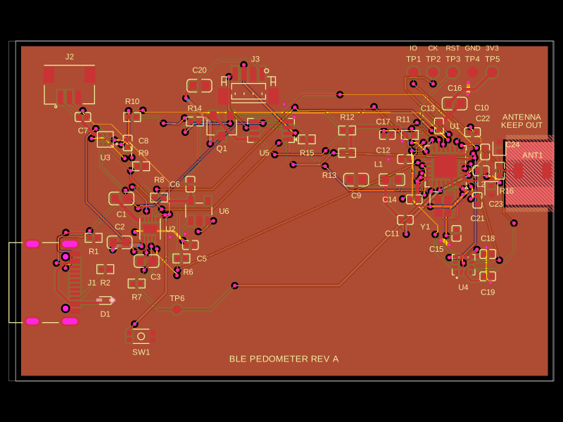 More from this authorAnasSarkiz/ble-pedometerThis code defines and configures various electronic hardware components such as surface-mount resistors, crystals, diodes, transistors, connectors, and switches with their physical footprints, schematic symbols, and 3D CAD models for PCB assembly.
 Similar packageaura/diy-power-delivery-triggerThis hardware design implements a USB Type-C port with supporting power management and signal conditioning components, including a USB-C connector, a FUSB302 USB-C port controller, ESD protection diodes, a buck converter for 3.3V power regulation, an STM32 microcontroller for control and processing, an RGB LED indicator, push button, terminal block connections, and associated filtering and support components.
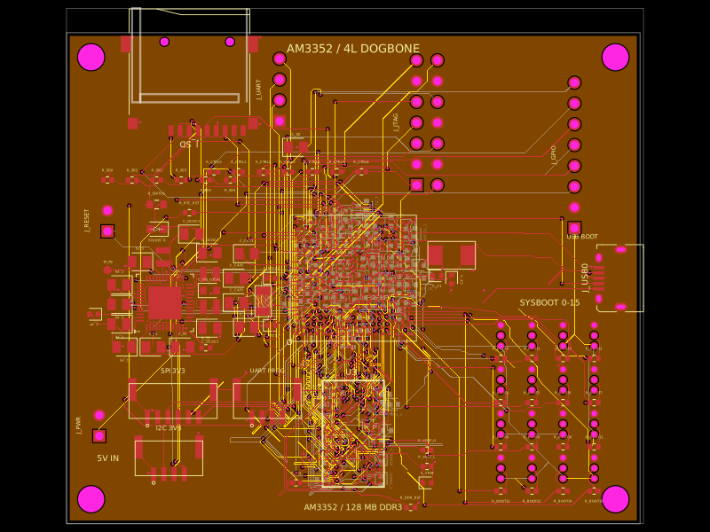 Discover something newseveibar/am3352-dev-board-4layer-dogboneDefines PCB footprints and pin mappings for a TI AM3352ZCZ100 processor, JST GH connectors, and assembly-part lookup helpers for capacitors, resistors, and headers.