AnasSarkiz/rp2040-usb-c-single-axis-dm542t-motion-controller--01a0e89c
A USB‑C RP2040 controller board with external QSPI flash, crystal clock, regulated 3.3/1.1/5 V power, boost-converted motor-driver supply, protected USB and limit inputs, status LEDs, reset/boot switches, and AO3400A MOSFET outputs for stepper-control signals.
- Version
- 0.1.0-prototype.19
- License
- unset
- Stars
- 0
BRING-UP.md
# Physical bring-up checklist — revision A0

**Pending. No physical board exists or has been tested.** Only perform these checks after design and fabrication gates pass. Record board serial/revision, assembly substitutions, firmware hash, instruments, driver label/revision, motor, supply, DIP settings and ambient conditions for each result.

- Inspect assembly orientation, solder bridges, exposed-pad joints, USB shell anchors and mounting clearances.
- Check unpowered rail resistance and absence of USB backfeeding.
- Power from a current-limited USB source; measure VBUS, 3.3 V, 1.1 V, current and regulator temperature.
- Measure current before enumeration (<100 mA), after configuration (<500 mA), inrush, and USB suspend (<2.5 mA); verify suspend entry/resume and both current-limit startup stages.
- Measure VDRV at each loaded driver pair over USB voltage/cable/temperature corners: require 4.5–5 V, allocated ripple ≤50 mV peak-to-peak, each cable loop ≤1 Ω. Verify short/overload limiting and firmware latch; only USB unmount/reset clears it.
- Confirm normal USB enumeration, both USB-C orientations, reset, BOOTSEL flash recovery and SWD access.
- With the motor supply isolated, scope STEP/DIR/ENA across startup, reset, bootloader, firmware crash/watchdog and USB cable removal. Record pulse widths, edge rates, startup glitches and minimum voltage at driver terminals.
- Connect only the selected DM542T V4.0 with S2 at 5 V and correct motor current settings. Verify ENABLE polarity and its controller-power-loss behavior.
- Verify positive/negative relative movement, configured speed/acceleration, STOP, invalid commands and pulse-count position reports.
- Test each limit using closed contact, open contact, disconnected wire, contact bounce and attempted travel toward/away from the limit.
- Exercise homing from both sides of the switch, already-active input, stuck switch, broken wire, opposite-limit activation, travel bound and timeout.
- Test host closure, unplug, USB suspend, missing heartbeat and reconnect. Record stopping latency and require explicit re-enable.
- Run the intended load over its operating range; measure rail current, temperatures and signal timing. Determine tested limits from measurements rather than design targets.
- Archive scope captures, setup photos, firmware/build identity and pass/fail results. Keep unresolved findings visible in VALIDATION.md.
Related Packages
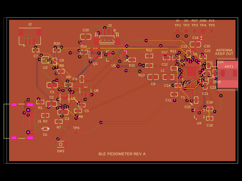 More from this authorAnasSarkiz/ble-pedometerThis code defines and configures various electronic hardware components such as surface-mount resistors, crystals, diodes, transistors, connectors, and switches with their physical footprints, schematic symbols, and 3D CAD models for PCB assembly.
 Similar packageaura/diy-power-delivery-triggerThis hardware design implements a USB Type-C port with supporting power management and signal conditioning components, including a USB-C connector, a FUSB302 USB-C port controller, ESD protection diodes, a buck converter for 3.3V power regulation, an STM32 microcontroller for control and processing, an RGB LED indicator, push button, terminal block connections, and associated filtering and support components.
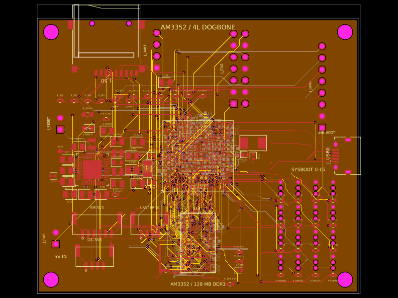 Discover something newseveibar/am3352-dev-board-4layer-dogboneDefines PCB footprints and pin mappings for a TI AM3352ZCZ100 processor, JST GH connectors, and assembly-part lookup helpers for capacitors, resistors, and headers.