AnasSarkiz/am625sip-linux
An electronic component representing an AM625 system-in-package with mapped pins and physical footprint for PCB integration.
- Version
- 1.0.3
- License
- unset
- Stars
- 0
validation/failed-native-inner-row/fanout-three-native.log
PCB
Schematic

Building 1 file(s)...
Building stages/02-inner-row-breakout.circuit.tsx...
Generating circuit JSON...
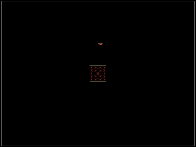
Wrote debug artifact: dist/autorouter-debug/placement-unrouted.png
Autorouting <group#469 name=".processor" /> phase 1 start: connections=3, obstacles=428, previous_traces=0
  connections: breakout:pcb_breakout_point_0, breakout:pcb_breakout_point_1, breakout:pcb_breakout_point_2
Wrote debug artifact: dist/autorouter-debug/phase-0.input.simple-route.json
  phase 1 error after 1.3s: Fanout failed for U1: only 2 of 3 connections could escape to the breakout boundary. The breakout boundary is 9.85mm from the pads at its narrowest point, which all 3 escapes have to share. Give the fanout more room by increasing the breakout's padding, or by extending the breakout to include the parts crowding it (decoupling capacitors, series resistors) so their pads sit inside the boundary instead of against it.
Wrote debug artifact: dist/autorouter-debug/phase-0.input.simple-route.json
Wrote debug artifact: dist/autorouter-debug/phase-0.error.json
Async effect error in PcbTraceRender "autorouting":
Error: Fanout failed for U1: only 2 of 3 connections could escape to the breakout boundary. The breakout boundary is 9.85mm from the pads at its narrowest point, which all 3 escapes have to share. Give the fanout more room by increasing the breakout's padding, or by extending the breakout to include the parts crowding it (decoupling capacitors, series resistors) so their pads sit inside the boundary instead of against it.
    at solveFanout (/Users/anassarkiz/Documents/Codex/2026-09-05/a-minimum-practical-ti-am625sip-linux/outputs/am625sip-linux/node_modules/@tscircuit/core/dist/index.js:34062:17)
    at startFanout (/Users/anassarkiz/Documents/Codex/2026-09-05/a-minimum-practical-ti-am625sip-linux/outputs/am625sip-linux/node_modules/@tscircuit/core/dist/index.js:34090:79)
    at <anonymous> (/Users/anassarkiz/Documents/Codex/2026-09-05/a-minimum-practical-ti-am625sip-linux/outputs/am625sip-linux/node_modules/@tscircuit/core/dist/index.js:34118:12)
Solver inputs written to /Users/anassarkiz/Documents/Codex/2026-09-05/a-minimum-practical-ti-am625sip-linux/outputs/am625sip-linux/dist/solver-debug/stages/02-inner-row-breakout/solver-inputs.json
Wrote debug artifact: dist/autorouter-debug/board.meta.json
Circuit JSON written to dist/stages/02-inner-row-breakout/circuit.json
TP_SD_CMD has no courtyard
TP_SD_D0 has no courtyard
TP_SD_D1 has no courtyard
All pins on U1 are underspecified (no pinAttributes set)
U1 has no pin with requires_power=true
U1 has no pin with requires_ground=true
Fanout failed for U1: only 2 of 3 connections could escape to the breakout boundary. The breakout boundary is 9.85mm from the pads at its narrowest point, which all 3 escapes have to share. Give the fanout more room by increasing the breakout's padding, or by extending the breakout to include the parts crowding it (decoupling capacitors, series resistors) so their pads sit inside the boundary instead of against it.
Ports [U1.A21, TP_SD_CMD.pin1] are not connected together through the same net.
Ports [U1.A22, TP_SD_D0.pin1] are not connected together through the same net.
Ports [U1.B21, TP_SD_D1.pin1] are not connected together through the same net.
Trace [.U1 > .A21 to .TP_SD_CMD > .pin1] is not connected (it has no PCB trace)
Trace [.U1 > .A22 to .TP_SD_D0 > .pin1] is not connected (it has no PCB trace)
Trace [.U1 > .B21 to .TP_SD_D1 > .pin1] is not connected (it has no PCB trace)
Generating preview images...
[stages/02-inner-row-breakout] Generating PCB SVG...
[stages/02-inner-row-breakout] Written pcb.svg
[stages/02-inner-row-breakout] Generating PCB PNG...
[stages/02-inner-row-breakout] Written pcb.png
[stages/02-inner-row-breakout] Generating schematic SVG...
[stages/02-inner-row-breakout] Written schematic.svg

Build complete
  Circuits  1 passed
  Options   pcb-png, svgs, autorouter-debug, autorouter-dump-srj, solver-debug
  Output    dist

⚠ Build completed with errors
Build exiting with code 0: build finished successfully