AnasSarkiz/NEMA14_RP2040
A NEMA motor assembly concept with a controller board, four proposed M3 screws and spacers, motor lead splices, and a JST 4-pin connector harness.
- Version
- 1.13.0
- License
- ISC
- Stars
- 0
docs/usb-programming.md
> Historical baseline document: this predates the opposite-edge v1.11.0 draft. See [current draft and blockers](opposite-edge-review.md) for current evidence.

# USB programming

1. Short the separate top-side `TP_BOOT` and `TP_BOOT_GND` pads to hold flash chip-select low through `R_BOOT` (1 kΩ).
2. While holding the short, connect the computer to **J_DATA** from a fully unpowered board, or momentarily short `TP_RUN` to `TP_GND` to reset the powered MCU.
3. Release the BOOT short after the ROM enters USB boot mode.
4. Copy a firmware UF2 built for this RP2040 board to the ROM's `RPI-RP2` drive, or use `picotool`.

Source: [RP2040 datasheet](https://datasheets.raspberrypi.com/rp2040/rp2040-datasheet.pdf), boot sequence and USB boot documentation. The QSPI flash, 12 MHz crystal, USB 27 Ω series resistors and required rails are present. There is no fitted BOOT button; use the exposed pads. SWD uses `TP_SWCLK`, `TP_SWDIO` and `TP_GND`; `TP_3V3` provides the target voltage reference. RUN uses `TP_RUN`. These seven bare top-side pads replace the former debug/boot strips and have no stencil paste or purchased assembly parts.

The **PD port is motor power only**, requesting 15 V. Programming uses the separate **Data USB-C port**. USB ROM entry connections and physical copper continuity have been checked in CAD. Enumeration, boot-ROM PHY operation at the chosen supply, and actual flashing must still be tested on an assembled prototype. No motor-control firmware has been implemented or preloaded. Keep the motor disconnected during the first flashing/rail checks.
Related Packages
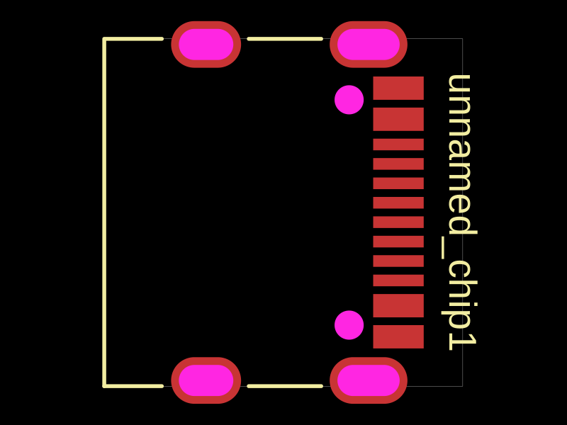 More from this authorAnasSarkiz/testDefines a PCB layout with a JST PH 2-pin connector labeled "J1".
 Similar packageimrishabh18/rp2040-motor-controllerAn RP2040-based NEMA17 stepper-motor controller with USB-C programming and PD motor-power negotiation, DRV8825 dual H-bridge drive, current/temperature telemetry, protected power filtering, status RGB LED, buzzer alarm, and optional magnetic encoder.
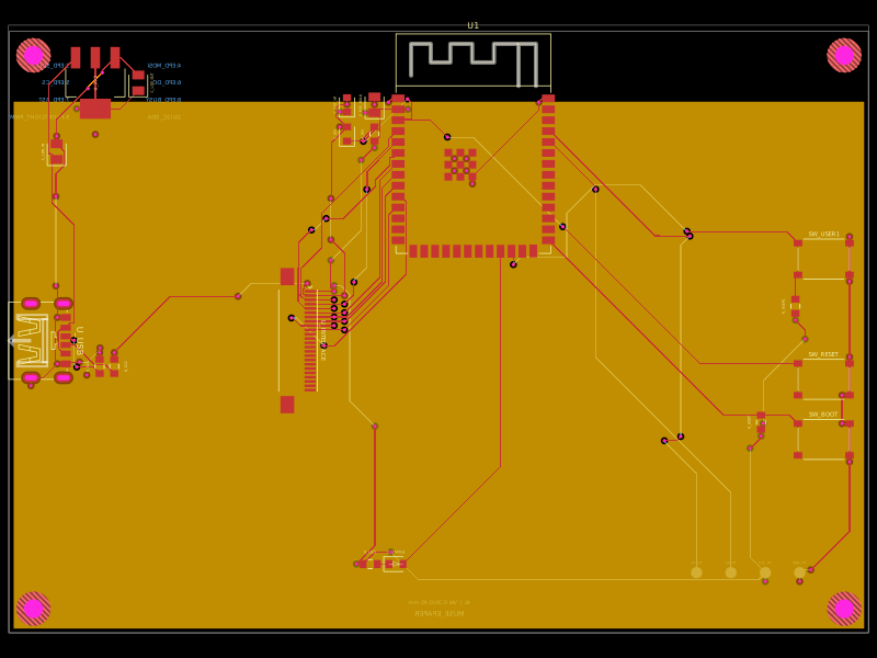 Discover something newShiboSoftwareDev/muse-reterminal-e1001-replacementA four-layer ESP32-S3 e-paper carrier board with USB-C power, AMS1117 3.3V regulation, 24-pin FFC interface, reset/boot and user buttons, status LED, decoupling passives, test points, mounting holes, and ground/power planes.