AnasSarkiz/NEMA14_RP2040
A NEMA motor assembly concept with a controller board, four proposed M3 screws and spacers, motor lead splices, and a JST 4-pin connector harness.
- Version
- 1.13.0
- License
- ISC
- Stars
- 0
docs/schematic-pin-alignment.md
# Schematic pin alignment, 1.12.2

The native USB-C schematic terminals are 0.40 schematic units outside their symbol boxes. The presentation generator previously assigned a 0.35-unit pin stem, leaving a 0.05-unit visible gap. The generator now derives that display length from the terminal and box positions. The saved drawings receive the same correction for all 16 displayed terminals on J_PD and J_DATA.

Only `schematic_port.distance_from_component_edge` changes. Pin endpoints, traces, symbols, labels, no-connect marks, electrical source records, PCB copper/footprints and mechanical CAD remain unchanged. Current assembly JSON includes the corrected schematic records, with its mechanical records preserved exactly. No current-sensing hardware or firmware is added.

All 32 changed stems per board were checked in the generated SVG against the actual box boundary. The six native A4 SVG/PNG sheets and vector PDF were refreshed. TypeScript and native Circuit JSON schema checks pass. `artifacts/schematic-pin-alignment/verification.json` binds the 1.12.1 baseline to this display-only correction; previous PCB and motor qualification records retain their original baseline hashes.
Related Packages
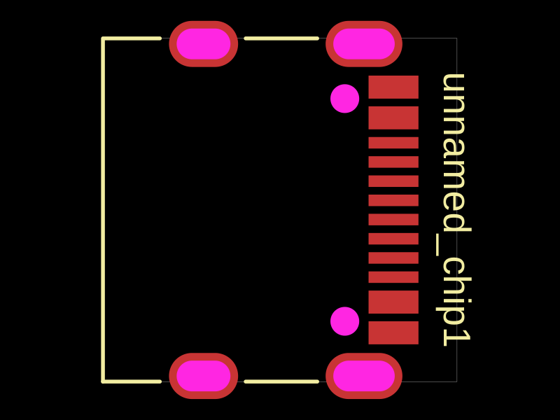 More from this authorAnasSarkiz/testDefines a PCB layout with a JST PH 2-pin connector labeled "J1".
 Similar packageimrishabh18/rp2040-motor-controllerAn RP2040-based NEMA17 stepper-motor controller with USB-C programming and PD motor-power negotiation, DRV8825 dual H-bridge drive, current/temperature telemetry, protected power filtering, status RGB LED, buzzer alarm, and optional magnetic encoder.
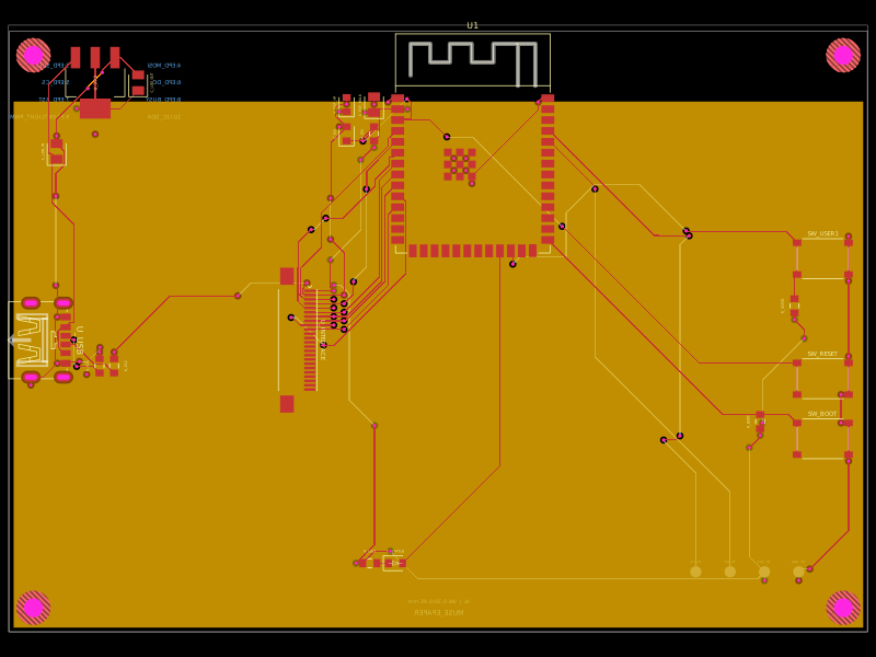 Discover something newShiboSoftwareDev/muse-reterminal-e1001-replacementA four-layer ESP32-S3 e-paper carrier board with USB-C power, AMS1117 3.3V regulation, 24-pin FFC interface, reset/boot and user buttons, status LED, decoupling passives, test points, mounting holes, and ground/power planes.