AnasSarkiz/NEMA14_RP2040
A NEMA motor assembly concept with a controller board, four proposed M3 screws and spacers, motor lead splices, and a JST 4-pin connector harness.
- Version
- 1.13.0
- License
- ISC
- Stars
- 0
docs/mounting-usb-verification.md
> Historical baseline document: this predates the opposite-edge v1.11.0 draft. See [current draft and blockers](opposite-edge-review.md) for current evidence.

# Current mounting and USB verification

Saved board SHA-256: `a261317dc5ba675ad0bc012489fdf99ec7cd64299d3db6f8985828f6757781d6`. Source, actual Gerber outline and Excellon drill files agree on 35 × 35 mm and four Ø3.2 mm NPTH holes at exactly (±13, ±13). Native STEP screening passes for the approved upward USB insertion, two defined 10 mm housings at 12.1 mm pitch, and a Ø4.4 × 3 mm head envelope around the required maximum Ø4 mm fastener heads.

The nominal cable-housing gap is 2.100 mm. Actual supplier footprints/courtyards and models are retained. See [engineering fixes](engineering-fixes.md), `artifacts/mechanical/mount-usb-screen.json`, `artifacts/mount-drill-verification.json` and the actual CAM audit for current evidence.

Both primary and order-review manufacturing archives pass their full CAM audits. Passive-orientation advisories remain reviewable in the native placement log. The publication gate rejects other diagnostics and any real geometry/CAM failure.

The manufacturer motor drawing dimensions front holes only. Rear motor fit, adapter geometry, physical cable/fastener tolerances, assembly stack/thread engagement and hardware operation remain unverified.
Related Packages
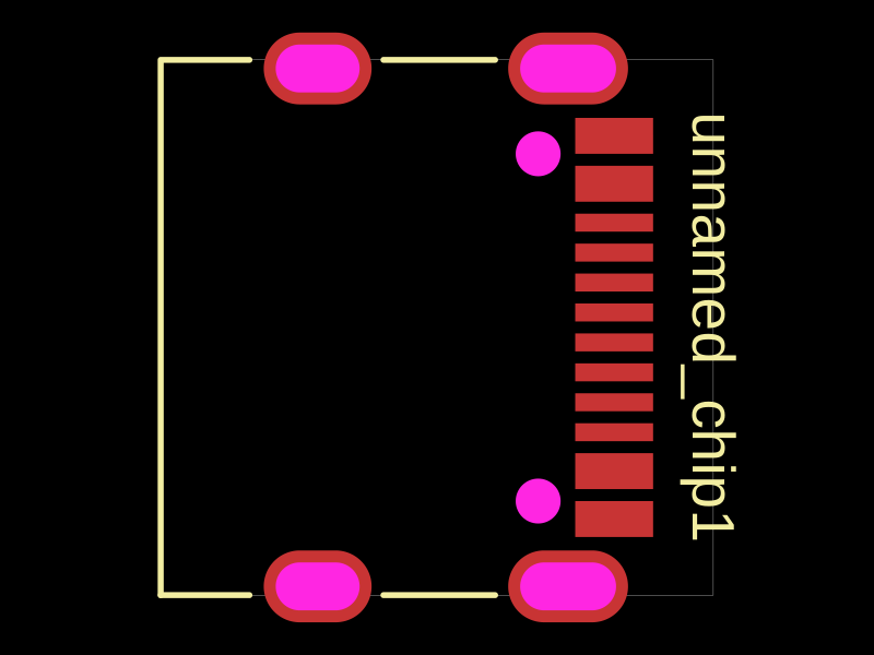 More from this authorAnasSarkiz/testDefines a PCB layout with a JST PH 2-pin connector labeled "J1".
 Similar packageimrishabh18/rp2040-motor-controllerAn RP2040-based NEMA17 stepper-motor controller with USB-C programming and PD motor-power negotiation, DRV8825 dual H-bridge drive, current/temperature telemetry, protected power filtering, status RGB LED, buzzer alarm, and optional magnetic encoder.
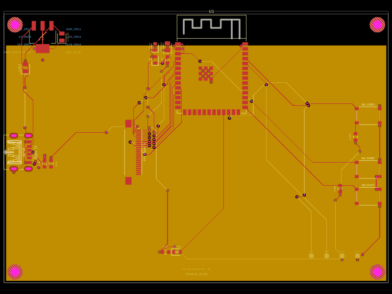 Discover something newShiboSoftwareDev/muse-reterminal-e1001-replacementA four-layer ESP32-S3 e-paper carrier board with USB-C power, AMS1117 3.3V regulation, 24-pin FFC interface, reset/boot and user buttons, status LED, decoupling passives, test points, mounting holes, and ground/power planes.