AnasSarkiz/NEMA14_RP2040
A NEMA motor assembly concept with a controller board, four proposed M3 screws and spacers, motor lead splices, and a JST 4-pin connector harness.
- Version
- 1.13.0
- License
- ISC
- Stars
- 0
docs/jst-restoration.md
> Historical baseline document: this predates the opposite-edge v1.11.0 draft. See [current draft and blockers](opposite-edge-review.md) for current evidence.

# Current motor connector and harness — v1.8.2

J_MOTOR is the original imported **BM04B-SRSS-TB(LF)(SN), C160390**, a 1 mm-pitch top-entry SMT JST-SH header. It follows the user's NEMA8 assembly reference. Rishabh's RP2040 reference uses the 2 mm-pitch through-hole **B4B-PH-K-S(LF)(SN), C131334** JST-PH. Coil order matches, but the two families cannot mate. Use an SH harness rather than a PHR-4 PH cable.

JST's [SH family datasheet](https://www.jst-mfg.com/product/pdf/eng/eSH.pdf), cached in `references/JST-SH.pdf`, specifies **1 A AC/DC with AWG28**, 50 V AC/DC, and −25 to +85 °C including current-induced temperature rise. Contacts accept AWG32–28 with insulation Ø0.4–0.8 mm. The proposed mating parts are **SHR-04V-S** housing and **SSH-003T-P0.2-H** crimp contacts. Use correctly crimped AWG28 harness wires to support the stated 1 A rating. Verify exact ordering suffix, supplier crimp capability and wire insulation before ordering.

At 3.3 V nominal, the A4988 divider and 0.24 Ω sense resistors set approximately 0.351 A peak per phase. The provisional tolerance budget is approximately 0.397 A; this is not a measured maximum. The SH family rating supports the nominal electrical requirement with the specified harness. It does not qualify enclosure temperature, vibration, strain relief, cable retention or the supplier's assembly process.

The STEPperONLINE 14HM11-0404S drawing specifies bare motor leads, not a factory JST harness. A properly terminated adapter harness or qualified splice is needed; do not assume the motor lead gauge fits SH contacts directly.

| Header pin | A4988 output net | Motor factory lead color |
| --- | --- | --- |
| 1 | A_PLUS | Black |
| 2 | A_MINUS | Green |
| 3 | B_PLUS | Red |
| 4 | B_MINUS | Blue |

The original imported land pattern has four signal lands and two NC mechanical hold-down lands, all on top. There are no JST through-hole leads or corresponding drill hits. The six physical land/CAM matches are recorded in `artifacts/jst-restoration/connector-verification.json`. The two hold-down pad numbers were split into distinct metadata identities for verification; original copper geometry is retained.

Native STEP landing-region overlap and nominal vertical insertion clearance pass. The supplier model fuses plastic and contacts, so those checks do not independently identify each metal terminal center. Harness housing tolerances, grip access, bend radius and strain relief need verification with the actual purchased harness. The assembly-preview model is a concept; no motor rear threads or adapter fit are verified.

All 81 fitted parts, including this connector, are included in the top SMT BOM/CPL. Eight USB shell joints still need secondary soldering. See [order-review instructions](jlcpcb-order-review.md). The earlier PH restoration is preserved separately in [the v1.4 history](history/v1.4-jst-restoration.md).
Related Packages
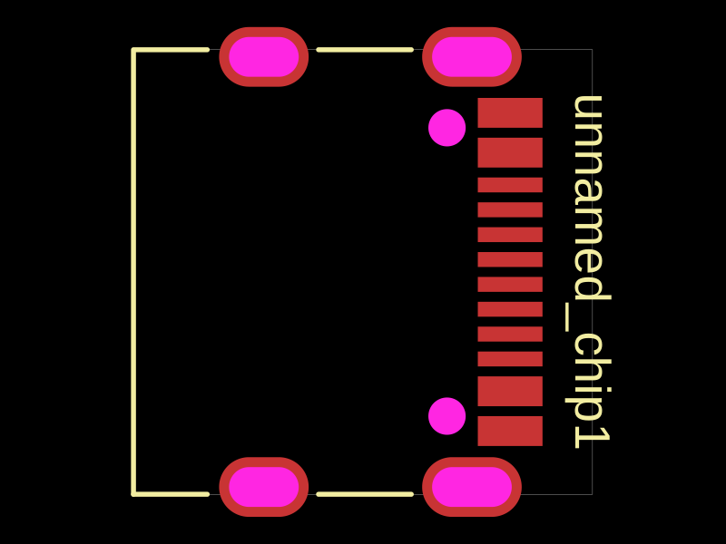 More from this authorAnasSarkiz/testDefines a PCB layout with a JST PH 2-pin connector labeled "J1".
 Similar packageimrishabh18/rp2040-motor-controllerAn RP2040-based NEMA17 stepper-motor controller with USB-C programming and PD motor-power negotiation, DRV8825 dual H-bridge drive, current/temperature telemetry, protected power filtering, status RGB LED, buzzer alarm, and optional magnetic encoder.
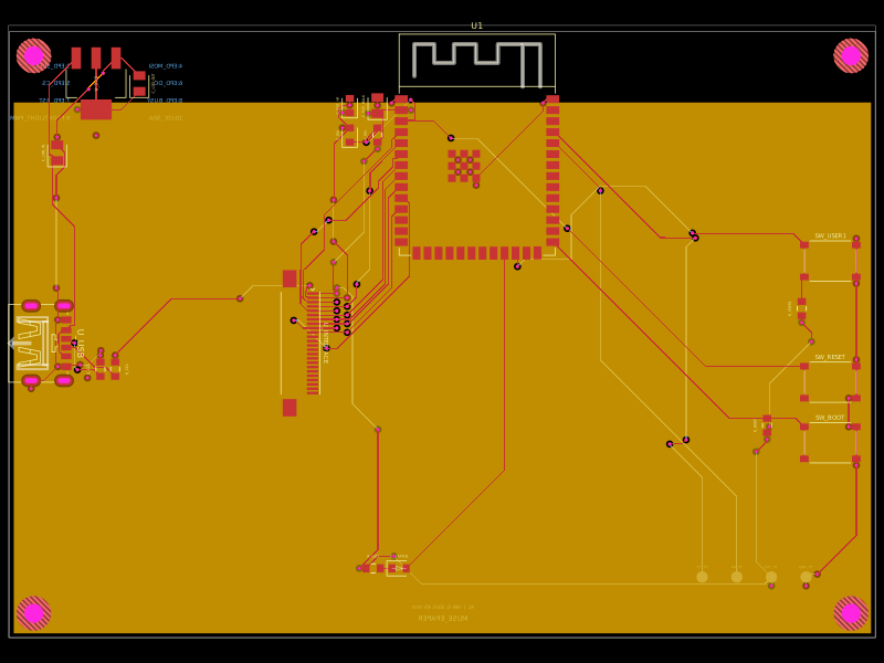 Discover something newShiboSoftwareDev/muse-reterminal-e1001-replacementA four-layer ESP32-S3 e-paper carrier board with USB-C power, AMS1117 3.3V regulation, 24-pin FFC interface, reset/boot and user buttons, status LED, decoupling passives, test points, mounting holes, and ground/power planes.