AnasSarkiz/NEMA14_RP2040
A NEMA motor assembly concept with a controller board, four proposed M3 screws and spacers, motor lead splices, and a JST 4-pin connector harness.
- Version
- 1.13.0
- License
- ISC
- Stars
- 0
docs/history/v1.4-mounting-usb-verification.md
# Same-edge USB and mounting verification — 2026-10-11
Review version: **1.4.0**. GitHub baseline: `9e83101567b428d581b6217fcee81c1ef0b4ab7b`.
Final board SHA-256: `fdfa722080d2923545b55bcbd6f9324d113b180ed76eee5c205b92c3f61dd83b`.
The PCB remains exactly **35 × 35 mm**, without an extension. Native source output, saved `artifacts/board.circuit.json`, delivery `index.circuit.json`, and the actual absolute-metric NPTH Excellon file all contain exactly four **Ø3.2 mm** holes at **(−13,−13), (−13,13), (13,−13), (13,13) mm**. The actual Gerber outline centreline spans −17.5 to +17.5 mm on both axes and encloses 1225 mm². See `mount-drill-verification.json` and `manufacturing/audit.json` for raw-file hashes, coordinate parsing and outline evidence.

## Same-edge connectors and required hardware
Both original C165948 TYPE-C-31-M-12 receptacles face outward along +Y. Their PCB anchors are (−6.2,12.1499711) and (6.2,12.1499711) mm at 180° PCB rotation. Their native CAD mouths are flush at (−6.2,17.5) and (6.2,17.5) mm, with **12.4 mm pitch**. Connector bezels may naturally protrude beyond the board edge; the PCB outline has no extension. The BOOT solder pads, protection parts and associated passives were repositioned to preserve access and avoid occupied space.
This layout requires the user-approved **M3 DIN 920 reduced heads, maximum Ø4 mm**. [DIN 920 dimensional table](https://www.aspenfasteners.com/content/pdf/Metric_DIN_920_spec.pdf) specifies M3 head maximum Ø4 mm; [a supplier's M3 DIN 920 listing](https://accu-components.com/us/reduced-slotted-pan-head-screws/65327-SFPR-M3-4-A2) specifies Ø4 +0/−0.18 mm. These references establish head dimensions, not a qualified screw length or rear-thread engagement. Ordinary Ø5.4 mm heads and larger washers are not supported by this screen.
All **62 fitted supplier STEP models, including the restored JST PH header** were hash-verified and transformed using the actual saved CAD records. Component/component, component/head, and simultaneous plug collision volumes are zero. Both USB bodies have at least **0.13 mm** clearance to the conservative **Ø4.4 × 3 mm** cylindrical head envelope. That envelope adds 0.2 mm radial allowance around the maximum Ø4 mm head; nominal maximum-head body clearance is approximately 0.33 mm. This is a defined screening allowance, not a complete assembly tolerance qualification.
Two simultaneous **12 × 30 × 7 mm maximum plug envelopes** begin outside the mating mouths and have **0.4 mm** mutual gap, with zero intersection with other components or fastener envelopes. Actual cable housing dimensions, strain relief and mating hardware must stay within that bound and still require sample testing. The ports remain externally accessible without moving the mounting pattern.
Circular radius-2.2 mm keepouts constrain every copper layer. `allowPlacements=true` lets intact rectangular supplier courtyards extend over the circular envelope; it does not waive copper clearance or physical body clearance. Exact STEP solids provide the separate component/head check. Native trace DRC also treats circular keepouts as bounding squares; affected trace routing satisfies that conservative check without suppressing its errors.
## Electrical function and actual copper
Every physical pin identity, component value, net and source connection equals the GitHub baseline. The only source-component metadata change is J_MOTOR gaining the fitted JST manufacturer and supplier identity. Original supplier imports and land patterns remain unchanged. Placement and affected signal/power/ground copper were changed; they are not claimed to equal the baseline. `mounting-change-proof.json` binds the final source, saved geometry, counts and function. The routing, repair, pruning and cleanup receipts record construction history, including routes subsequently replaced; current board JSON and the final proof define the delivered geometry.
Retained legal copper was exported as fixed DSN input, affected copper rerouted with Freerouting, and physical opens and obsolete tails repaired against actual native pad geometry. Duplicate thermal vias and unanchored signal copper were removed. Ground fills were regenerated with 0.20 mm foreign-net clearance and 0.35 mm edge inset, retaining anchored regions. RP2040 main PD feeders use **0.55 mm** for the retained 0.75 A screening budget. Narrower 0.3 mm terminal branches use a 0.4 A budget only when a physical cut isolates exactly one VBB1/VBB2 or C_VCP terminal, as recorded in the width audit. This screen does not qualify current or temperature on hardware.
Final counts: **544 traces, 113 vias, 10 ground regions**. All **48 physical connectivity groups** are connected across all copper layers. Actual CAM has zero shorts, opens, unconnected pads or unexpected copper islands. Copper and drill geometry match the saved source within the documented parser tolerances. Actual distinct-conductor minimum spacings and mount/edge clearances are recorded in `artifacts/manufacturing/audit.json`; finished copper clears every circular keepout and meets the declared conductor and outline spacing rules. Raw export files are retained unchanged.
## Executed checks
Native DRC: **zero errors and zero warnings**. Native source compilation, netlist, source/pin checks, schematic placement, all-layer Gerber shorts and actual copper-width screening pass. Native placement returns exit 1 for passive-orientation suggestions; its placement DRC itself reports zero errors/warnings. Suggestions remain visible in the log. Complete independent CAM returns FAIL for the assembly findings below; no blanket all-checks PASS is claimed.
| Check | Result | Log |
|---|---|---|
| typescript | PASS | `artifacts/validation-resume/typescript.txt` |
| drc | PASS | `artifacts/validation-resume/drc.txt` |
| connectivity | PASS | `artifacts/validation-resume/connectivity.txt` |
| fitted_JST_and_actual_drills | PASS | `artifacts/validation-resume/fitted_JST_and_actual_drills.txt` |
| exact_mounts_and_actual_drills | PASS | `artifacts/validation-resume/exact_mounts_and_actual_drills.txt` |
| native_json_checks | PASS | `artifacts/validation-resume/native_json_checks.txt` |
| native_netlist | PASS | `artifacts/validation-resume/native_netlist.txt` |
| native_pin_specification | PASS | `artifacts/validation-resume/native_pin_specification.txt` |
| native_source | PASS | `artifacts/validation-resume/native_source.txt` |
| native_schematic-placement | PASS | `artifacts/validation-resume/native_schematic-placement.txt` |
| native_placement | FAIL — findings retained | `artifacts/validation-resume/native_placement.txt` |
| gerber_shorts | PASS | `artifacts/validation-resume/gerber_shorts.txt` |
| copper_widths | PASS | `artifacts/validation-resume/copper_widths.txt` |
| full_independent_CAM | FAIL — findings retained | `artifacts/validation-resume/full_independent_CAM.txt` |
Native STEP mechanical screen: **PASS**, bound to the exact current board hash in `artifacts/mechanical/mount-usb-screen.json`. Independent renders of the actual raw Gerbers are retained in `artifacts/manufacturing/independent-render/`.
## Remaining blockers
Complete manufacturing audit: **FAIL**. Finding classes: `BOM-source-identity`, `EP-stencil-coverage`, `assembly-paste-policy`, `assembly-table-policy`, `paste-source-mismatch`, `silkscreen-clearance`, `stencil-release-screen`. Bare solder interfaces remain in raw BOM/CPL, some BOM identities and paste layers disagree with source/assembly policy, fine-pitch and exposed-pad stencil checks fail, and silkscreen overlaps mask openings. Assembler pickup and pin-1 rotations remain unverified. These assembly issues prevent a fabrication/assembly approval; they are retained in the published prototype evidence.
**Rear-motor compatibility remains unverified.** The [14HM11-0404S manufacturer drawing](https://www.omc-stepperonline.com/download/14HM11-0404S.pdf) dimensions front mounting at 26 ± 0.2 mm with M3 threads, minimum 4 mm depth. It does not establish usable rear end-cap holes. This screen includes no verified motor or rear adapter, thread engagement, torque, washer/spacer stack or motor-wire/shaft clearance. Matching PCB holes alone establishes no rear fit.
Physical assembly, USB flashing/enumeration, PD negotiation, disabled startup, phase current, regeneration, thermal behavior, impedance/EMI and complete assembly tolerances still require hardware validation. **PROTOTYPE FABRICATION READY: NO.**
Publication preserves the reviewed saved copper and pins unchanged supplier CAD bytes to the pushed GitHub revision. `artifacts/publication-provenance.json` in the registry package records hashes and proves that only CAD URL metadata changes during packaging. Public downloads are checked separately by `scripts/verify-publication.py`.
### JST restoration in 1.4.0
The motor connection is now the reference’s fitted JST PH B4B-PH-K-S(LF)(SN), C131334, rather than four bare solder holes. Its body is inside the unchanged PCB outline, the four original STEP leads align with native PCB drill centres, and a 20 mm-high vertical insertion region above the body is clear of other fitted components, head envelopes and USB plug envelopes. The region adds 0.3 mm around the native header bounds; it is a geometric access screen, not a qualified cable, finger/grip, or full tolerance envelope. Its through-hole tails project approximately 1.4 mm below the board and must be accommodated by any rear adapter. Original source ports/nets/traces and all other component values are preserved; only J_MOTOR gains supplier identity. See [JST restoration](jst-restoration.md).
Related Packages
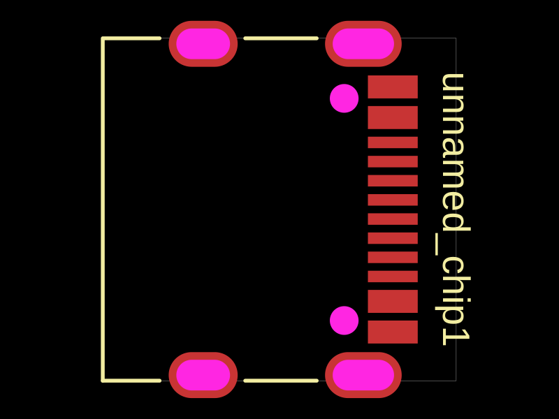 More from this authorAnasSarkiz/testDefines a PCB layout with a JST PH 2-pin connector labeled "J1".
 Similar packageimrishabh18/rp2040-motor-controllerAn RP2040-based NEMA17 stepper-motor controller with USB-C programming and PD motor-power negotiation, DRV8825 dual H-bridge drive, current/temperature telemetry, protected power filtering, status RGB LED, buzzer alarm, and optional magnetic encoder.
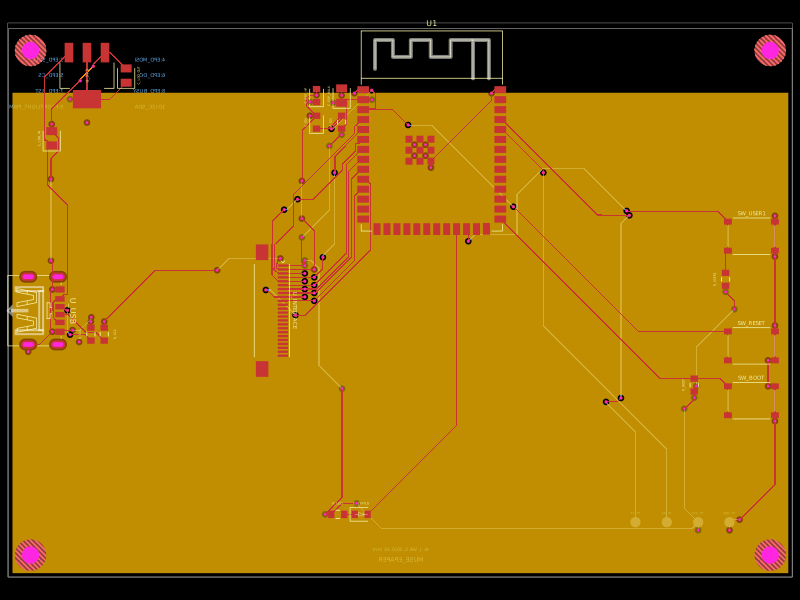 Discover something newShiboSoftwareDev/muse-reterminal-e1001-replacementA four-layer ESP32-S3 e-paper carrier board with USB-C power, AMS1117 3.3V regulation, 24-pin FFC interface, reset/boot and user buttons, status LED, decoupling passives, test points, mounting holes, and ground/power planes.