AnasSarkiz/NEMA14_RP2040
A NEMA motor assembly concept with a controller board, four proposed M3 screws and spacers, motor lead splices, and a JST 4-pin connector harness.
- Version
- 1.13.0
- License
- ISC
- Stars
- 0
docs/history/v1.4-jst-restoration.md
# Fitted JST PH motor connector restoration — 1.4.0

The 1.3.0 board contained four bare 2 mm-pitch solder holes, not a purchased JST connector. This release adds the reference board’s actual **B4B-PH-K-S(LF)(SN), C131334** top-entry JST PH header and original supplier land pattern and OBJ/STEP files. Use a matching **PHR-4** housing. Pins 1–4 remain A+, A−, B+, B−; all source port/net/trace records and all other component values are identical to the 1.3.0 baseline.

The exact PCB is still 35 × 35 mm. Both USB-C ports remain on +Y at X=±6.2 mm, with 12 mm plug envelopes and mandatory DIN 920 M3 heads ≤Ø4 mm. The mounting holes remain exactly (±13, ±13), Ø3.2 mm in native source, delivered Circuit JSON and the actual Excellon file.

## Verified geometry

The JST native land pattern uses four Ø0.999998 mm drills with Ø1.5999968 mm copper lands and 1.999996 mm supplier pitch. Nominal procurement dimensions are 1 mm drills / 2 mm pitch. The actual CAM coordinate comparison uses 0.0001 mm tolerance for decimal export rounding. The JSON coordinates are recorded below; actual Gerber drill matches are saved in `artifacts/jst-restoration/connector-verification.json`.

The original STEP lead centres measured in a Z=-2 mm section are X=0, 2, 4, 6 mm, Y=0 mm. The native footprint’s bounding-box centre differs from its anchor by 0.550037 mm. A rotated local CAD-only +Y correction aligns the STEP leads to the unchanged native land pattern. The original STEP and OBJ bytes and all original imported parts remain unchanged. Only access metadata (`insertionDirection="from_above"`) and model alignment are added to the new JST import.

The transformed header body fits inside the PCB outline. Its 20 mm-high vertical insertion region, extending 0.3 mm around the native header XY bounds, intersects no other fitted part, screw envelope or USB plug envelope. This screen does not qualify a particular cable, finger/grip envelope, tolerance stack or installed motor. Through-hole tails project approximately 1.4 mm below the PCB; any adapter must provide clearance and insulation. **Rear-motor compatibility is unverified.**

| Physical pin | Coil | Native X (mm) | Native Y (mm) | Actual drill X (mm) | Actual drill Y (mm) |
| --- | --- | --- | --- | --- | --- |
| 1 | A_PLUS | -7.499994 | -14.249963 | -7.5000 | -14.2500 |
| 2 | A_MINUS | -5.499998 | -14.249963 | -5.5000 | -14.2500 |
| 3 | B_PLUS | -3.500002 | -14.249963 | -3.5000 | -14.2500 |
| 4 | B_MINUS | -1.500006 | -14.249963 | -1.5000 | -14.2500 |

## Copper routing

The driver and local sense/charge-pump/decoupling parts are repositioned to clear the fitted header. The crystal body remains in place. Affected copper is reconstructed on the original four-layer stack with all physical nets checked. Motor and sense routes use 0.3 mm fan-outs, retaining the reviewed 0.4 A screening budget; this budget does not certify the programmed current or temperature in hardware. The main PD feeder uses 0.55 mm for the 0.75 A screening budget. A narrower internal PD branch receives a 0.4 A budget only when removing it physically isolates exactly one VBB1/VBB2 or C_VCP terminal, as recorded in the width audit. Three original exposed-pad ground thermal sites are the only allowed via-in-pad exceptions.

## Validation and remaining blockers

Native copper DRC reports zero errors and warnings; physical connectivity, native netlist/pin/source/schematic-placement checks, actual Gerber shorts, width review, native STEP mechanical checks, exact mounting drills and JST drills pass. Placement checks still return passive orientation suggestions. Full independent CAM remains FAIL for BOM/source identity, exposed-pad stencil coverage, paste/assembly-table policy, paste/source mismatch, silkscreen clearance and stencil manufacturability. The raw native BOM includes C131334 correctly but uses supplier identifiers as chip/connector values rather than complete MPN columns; supplier pickup rotation and assembly preview remain unverified. Header and USB cable insertion, USB/PD operation, current accuracy and temperature still need assembled-hardware testing. **Prototype only; fabrication approval is not granted.**

See `artifacts/resume-validation.json` for actual exit codes and `artifacts/mounting-change-proof.json` for the final frozen-file proof. Construction routing receipts contain replaced attempts; the final Circuit JSON, Gerbers and current audit reports define this release.
Related Packages
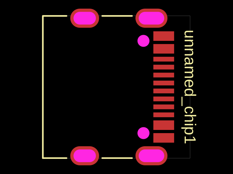 More from this authorAnasSarkiz/testDefines a PCB layout with a JST PH 2-pin connector labeled "J1".
 Similar packageimrishabh18/rp2040-motor-controllerAn RP2040-based NEMA17 stepper-motor controller with USB-C programming and PD motor-power negotiation, DRV8825 dual H-bridge drive, current/temperature telemetry, protected power filtering, status RGB LED, buzzer alarm, and optional magnetic encoder.
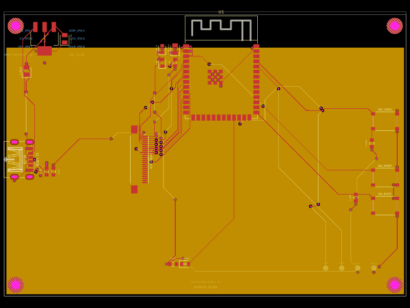 Discover something newShiboSoftwareDev/muse-reterminal-e1001-replacementA four-layer ESP32-S3 e-paper carrier board with USB-C power, AMS1117 3.3V regulation, 24-pin FFC interface, reset/boot and user buttons, status LED, decoupling passives, test points, mounting holes, and ground/power planes.