AnasSarkiz/NEMA14_RP2040
A NEMA motor assembly concept with a controller board, four proposed M3 screws and spacers, motor lead splices, and a JST 4-pin connector harness.
- Version
- 1.13.0
- License
- ISC
- Stars
- 0
docs/ai-review-assessment.md
> Historical baseline document: this predates the opposite-edge v1.11.0 draft. See [current draft and blockers](opposite-edge-review.md) for current evidence.

> Historical baseline assessment before the engineering fixes. Current results and resolved issues are in [engineering fixes](engineering-fixes.md).

# AI review assessment — RP2040 v1.8.2

Assessed against GitHub main `e04df7a3b606b280389109405de96601e9430695`, fetched on 2026-10-13, and saved board SHA-256 `567b45bd3737600dee1f833c4ee0692e6d50375be05031324674f744f09bd12e`. Rishabh's latest registry release remains v1.0.42 (`e8d285f7-c3d8-46f5-9a54-344fdde0124e`), the same reference captured by the existing pin review. The pasted text is predominantly an implementation checklist; it does not itself establish electrical failures, supplier acceptance or hardware results.

## Confirmed findings and corrections

The review correctly identified stale repository manufacturing/reference documents. Additional stale boot, firmware, mounting, connector and routing instructions were also found. They described JST-PH, bottom assembly, removed debug strips, 12 mm cable housings, older board hashes, or a signal-free inner1 plane. Current documentation now describes the actual SMT JST-SH, 81 top-side fitted parts, seven bare top-side test pads, approved 10 mm housings and saved copper. The order-package generator now copies its current instructions into the repository handoff document, avoiding a separate stale copy.

The validation gates now accept only the known orientation suggestions with zero placement DRC errors and warnings; an orientation summary alone no longer bypasses real failures. Rejection checks cover actual errors, warnings, unknown suggestions and trailing diagnostics. No source electrical connection, component placement, USB spacing, copper, Gerber, drill, BOM/CPL or published release was changed by this assessment. Documentation changes are on a separate branch. The current public version remains v1.8.2; its original publication receipt remains evidence for that release.

| Review claim | Evidence / assessment |
| --- | --- |
| Bottom-side assembly or PH motor connector | True of older documentation, false of the delivered v1.8.2 board. CPL has 81 TOP rows; JST-SH C160390 is included. |
| Raw CAM FAIL versus corrected CAM PASS | Both are true for different inputs. Raw audit is bound to the saved board; corrected audit is bound to the order source. Corrected copper/mask/outline/drills are byte-identical to raw fabrication members. |
| Eight shell THT joints | Confirmed by the eight actual plated USB slots. Single-face component population still needs secondary shell soldering. |
| Three exposed-pad thermal vias | Confirmed in the process CSV: U_MCU, U_DRV and U_PD. The requested fill/cap/planarize process has not been accepted by a supplier. |
| C_DV23, R_REF_H, C_TEMP orientation findings | Native placement advisories, with zero placement DRC errors/warnings. A suggested passive rotation is not proof of a wiring defect. No part was moved to silence these suggestions. |
| Generic Circuit JSON incompatibility | Confirmed: numeric display offsets, null optional owners and unsupported simple_buzzer classification in the installed generic schema. Physical coordinate/pin checks do not resolve importer compatibility. Metadata recovery remains separate work. |
| JST-SH suitability | Manufacturer family rating is 1 A with AWG28, above nominal 0.351 A phase current. SHR-04V-S and SSH-003T-P0.2-H support a separately terminated harness. SH and Rishabh's PH are not interchangeable. Harness assembly/fit remain unverified. |

## Electrical scope and remaining design review

Both USB connectors retain the physical C165948 terminal numbering. The DATA connector duplicates DP/DM contacts, uses independent 5.1 kΩ CC-to-ground resistors, connects fixed DATA_VBUS to the ESD rail and diode-OR input, and uses 27 Ω MCU series resistors. The PD connector connects CC1/CC2 to CH224A, leaves DP/DM/SBU NC, and supplies PD_VBUS. All four shell contacts on each connector are grounded. These net/pad assignments are checked independently; a working reference does not qualify this board's routing or firmware.

| Cable mode | Intended behavior; hardware validation still required |
| --- | --- |
| DATA only | Logic powers through D_DATA and the buck; motor remains disabled without valid PD/VM and initialized firmware. Test low-VBUS buck headroom, boot and enumeration in both orientations. |
| PD only | Logic powers through D_PD; CH224A requests 15 V, not guaranteed from every charger. RGB anode on DATA_VBUS remains unpowered. Test fallback, PG indication and firmware gating. |
| Both | PD normally supplies the common logic input; the two Schottky diodes isolate positive input rails. Verify reverse leakage/backfeed and all attach/detach sequences; shared ground remains common. |

The native source sets CH224A CFG1 through 56 kΩ to GND, with CFG2/3 unconnected, for a 15 V request. ENABLE_N has a 100 kΩ pull-up and SLEEP a 100 kΩ pull-down. These defaults provide reset disable; they do not supply motor-control firmware or an independently hardware-qualified PD interlock. The driver nominal peak is `3.3 × 10/(39+10)/(8 × 0.24) = 0.3508 A`; the provisional tolerance budget is 0.3969 A. Actual phase current, sense offsets, ground-return behavior, torque and thermal margins need measurement.

A new explicit review gap is the actual USB layer usage. MCU_DP includes 3.413 mm of inner1 copper while MCU_DM uses only top/bottom; connector-side DP and DM also differ in their layer usage. Whole-net copper totals are not pair skew. Current connectivity, clearance and plane-area checks do not qualify coupling, impedance, reference continuity or transitions. See [routing evidence and limitations](routing.md). This requires layout/stackup review and, if necessary, corrected pair routing followed by full revalidation.

Buck stability/input loops, host-only voltage headroom, motor regeneration/SMF18A energy and clamp margins, local heating, clock startup, USB/PD behavior and firmware remain unqualified. The fresh raw CAM parser reports 35 unassigned islands, all classified as intentional native NC pads (unused pins and mechanical tabs), with zero unknown islands. No physical assembly or bench test has occurred.

## Supplier and mechanical blockers

The corrected order package is prepared for engineering review. Supplier stock, exact MPN acceptance, polarized-part/pin-1 rotation and pickup datums, stencil/reflow process, filled/capped thermal vias, solder-mask capability and shell soldering still need acceptance. No substitutions are authorized by this report.

Current JLCPCB Economic versus Standard PCBA process support and panel requirements have not been verified. This environment's destination policy does not include jlcpcb.com, so live JLCPCB service rules were not retrieved. Do not assert that Standard is required or fabricate a supposedly compliant panel from unverified rail/fiducial rules. Supplier acceptance of the actual process must determine the assembly tier and panel specification; the functional PCB stays 35 × 35 mm.

Nominal supplier STEP/body/courtyard and cable/screw screens pass under the defined 10 mm cable-housing and ≤Ø4 mm DIN920 head assumptions. Actual harness bend/grip space, fastener tolerance stack, insulation, adapter and rear threads remain unverified. The motor drawing specifies front mounting only; the visual motor/harness assembly is a concept.

## Readiness classification

- **CAD geometric checks:** qualified only to the stated DRC, connectivity, clearance, pin, drill and nominal mechanical scope. USB signal-integrity and other electrical-layout qualification remain open.
- **Supplier review:** corrected package prepared for engineering assessment, with explicit process questions and design limitations.
- **Prototype order approved:** no.
- **Production qualified:** no.

Fresh check logs and the board-hash-bound receipt are in `artifacts/ai-review`. The fresh raw export initially differed from the previous extracted copy only in export-date headers. The extracted files were refreshed and the independent raw-CAM audit repeated; the first unsuccessful synchronization attempt is retained in its log. `reexport-consistency.json` verifies that every export member matches the published native export except those explicitly listed date headers. Actual failures or blocked reruns remain visible; historical reports are not substituted for rerun results. CH32 was outside the uploaded RP2040-specific checklist and was not changed in this assessment.
Related Packages
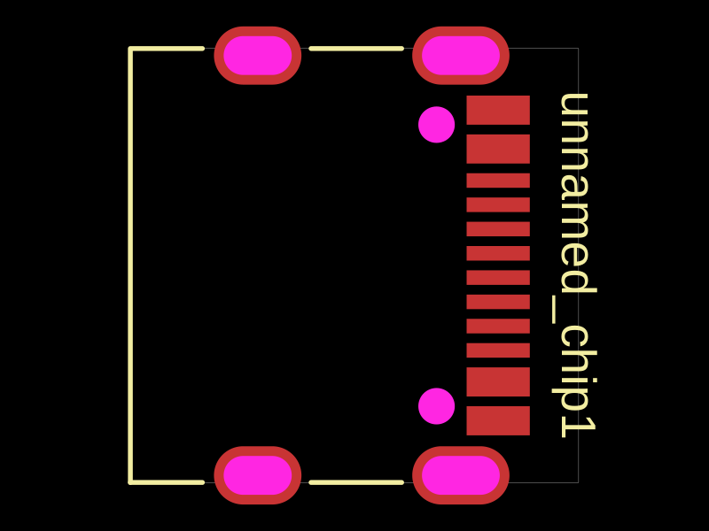 More from this authorAnasSarkiz/testDefines a PCB layout with a JST PH 2-pin connector labeled "J1".
 Similar packageimrishabh18/rp2040-motor-controllerAn RP2040-based NEMA17 stepper-motor controller with USB-C programming and PD motor-power negotiation, DRV8825 dual H-bridge drive, current/temperature telemetry, protected power filtering, status RGB LED, buzzer alarm, and optional magnetic encoder.
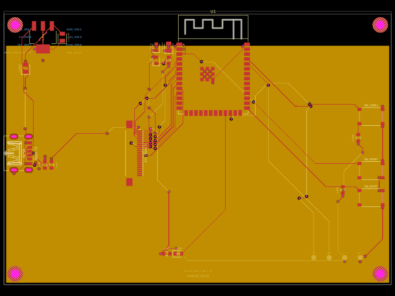 Discover something newShiboSoftwareDev/muse-reterminal-e1001-replacementA four-layer ESP32-S3 e-paper carrier board with USB-C power, AMS1117 3.3V regulation, 24-pin FFC interface, reset/boot and user buttons, status LED, decoupling passives, test points, mounting holes, and ground/power planes.